


Request Quote
(Ships tomorrow)
IRFR310TR N-Channel MOSFET 400V 1.7A DPAK Equivalent & Substitute Parts
Part Overview
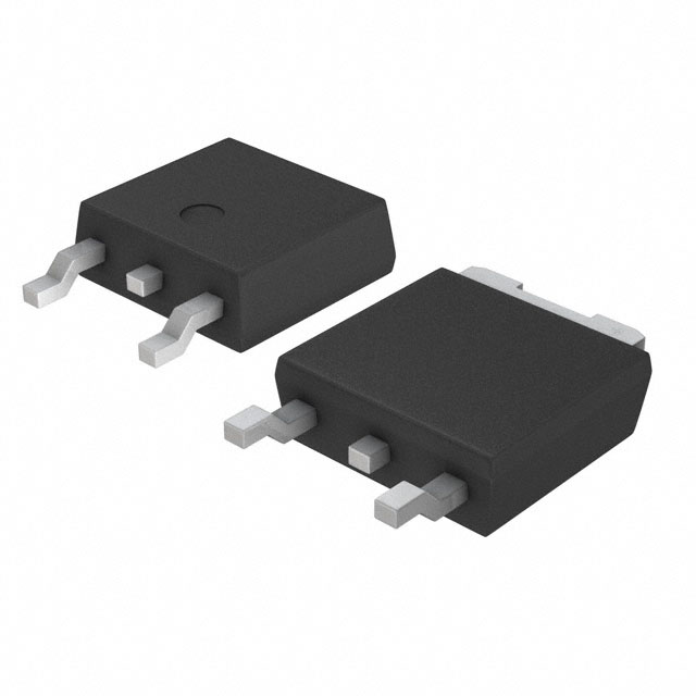
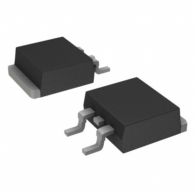
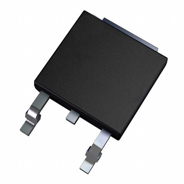
The IRFR310TR is an N-Channel Metal Oxide Semiconductor Field Effect Transistor (MOSFET) manufactured by Vishay Siliconix, rated for 400V drain-to-source voltage with 1.7A continuous drain current in a surface mount DPAK package. This device is classified as obsolete, necessitating identification of active equivalent and substitute parts for new designs and production continuity. The IRFR310TR remains in inventory with 2460 pieces available as new original stock. Equivalent parts maintain identical or superior electrical characteristics while substitute parts offer enhanced performance parameters within the same package family.
Substiute Parts
Key Parameters
| Parameter | Value | Unit |
|---|---|---|
| Drain to Source Voltage (Vdss) | 400 | V |
| Continuous Drain Current (Id) @ 25°C | 1.7 | A (Tc) |
| On-State Resistance (Rds On) @ 1A, 10V | 3.6 | Ohm |
| Gate Threshold Voltage (Vgs(th)) @ 250µA | 4 | V |
| Gate Charge (Qg) @ 10V | 12 | nC |
| Input Capacitance (Ciss) @ 25V | 170 | pF |
| Power Dissipation (Max) | 2.5 (Ta), 25 (Tc) | W |
| Operating Temperature Range | -55 to 150 | °C (TJ) |
| Package Type | TO-252-3, DPAK | Surface Mount |
| Gate Voltage (Max) | ±20 | V |
Substitute Part Grouping Explanation
Substitution of the IRFR310TR is determined by strict adherence to the following electrical and mechanical parameters:
Primary Substitution Criteria:
- Drain to Source Voltage (Vdss): Minimum 400V
- Package Type: TO-252-3 DPAK surface mount configuration
- FET Type: N-Channel Metal Oxide technology
- Operating Temperature Range: Minimum -55°C to 150°C
- Mounting Type: Surface Mount
Secondary Compatibility Parameters:
- On-State Resistance (Rds On): Equal or lower values indicate improved performance
- Continuous Drain Current (Id): Equal or higher values provide design margin
- Gate Charge (Qg): Lower values reduce switching losses
- Input Capacitance (Ciss): Lower values improve switching speed
Parametric equivalents (IRFR310TRLPBF, IRFR310TRPBF, IRFR310TRPBF-BE3) maintain identical electrical specifications with differences in packaging format and RoHS compliance status. Manufacturer-recommended substitutes (AOD3N40, FDD3N40TM, TN2640K4-G) offer enhanced performance characteristics while maintaining voltage and package compatibility.
Parameter Comparison
| Part Number | Manufacturer | Vdss (V) | Id @ 25°C (A) | Rds On @ 1A, 10V (Ohm) | Vgs(th) @ 250µA (V) | Qg @ 10V (nC) | Ciss @ 25V (pF) | Power Dissipation (W) | Product Status | RoHS Status |
|---|---|---|---|---|---|---|---|---|---|---|
| IRFR310TR | Vishay Siliconix | 400 | 1.7 | 3.6 | 4 | 12 | 170 | 2.5 (Ta), 25 (Tc) | Obsolete | Non-compliant |
| IRFR310TRLPBF | Vishay Siliconix | 400 | 1.7 | 3.6 | 4 | 12 | 170 | 2.5 (Ta), 25 (Tc) | Active | ROHS3 Compliant |
| IRFR310TRPBF | Vishay Siliconix | 400 | 1.7 | 3.6 | 4 | 12 | 170 | 2.5 (Ta), 25 (Tc) | Active | ROHS3 Compliant |
| IRFR310TRPBF-BE3 | Vishay Siliconix | 400 | 1.7 | 3.6 | 4 | 12 | 170 | 2.5 (Ta), 25 (Tc) | Active | ROHS3 Compliant |
| AOD3N40 | Alpha & Omega Semiconductor Inc. | 400 | 2.6 | 3.1 | 4.5 | 5.1 | 225 | 50 (Tc) | Active | ROHS3 Compliant |
| FDD3N40TM | onsemi | 400 | 2 | 3.4 | 5 | 6 | 225 | 30 (Tc) | Active | ROHS3 Compliant |
| TN2640K4-G | Microchip Technology | 400 | 0.5 | 5 | 2 | N/A | 225 | 2.5 (Ta) | Active | ROHS3 Compliant |
Engineering Selection Recommendations
Direct Parametric Equivalents (Recommended for Obsolescence Replacement):
IRFR310TRLPBF and IRFR310TRPBF are direct parametric equivalents to the IRFR310TR, maintaining identical electrical specifications across all measured parameters. Both parts are manufactured by Vishay Siliconix and carry ROHS3 compliance certification. IRFR310TRPBF offers the highest inventory availability (51,988 pieces) and is suitable for immediate production deployment. IRFR310TRPBF-BE3 provides identical electrical performance with Tape & Reel packaging and REACH Affected status, appropriate for applications requiring specific regulatory documentation.
Performance-Enhanced Substitutes:
AOD3N40 (Alpha & Omega Semiconductor) provides 52.9% higher continuous drain current (2.6A vs. 1.7A) and 13.9% lower on-state resistance (3.1 Ohm vs. 3.6 Ohm), with significantly improved power dissipation capability (50W vs. 25W at Tc). This device is suitable for applications requiring enhanced thermal performance and current handling.
FDD3N40TM (onsemi UniFET™ series) delivers 17.6% higher continuous drain current (2A vs. 1.7A) and 5.6% lower on-state resistance (3.4 Ohm vs. 3.6 Ohm), with 20% improved power dissipation (30W vs. 25W at Tc). Gate charge is reduced by 50% (6 nC vs. 12 nC), reducing switching losses in high-frequency applications.
Limited Current Application:
TN2640K4-G (Microchip Technology) maintains 400V voltage rating and DPAK packaging but is rated for only 500mA continuous drain current, representing a 70.6% reduction from the IRFR310TR specification. This device is suitable only for low-current applications and is not recommended as a general substitute.
All recommended substitutes maintain the TO-252-3 DPAK surface mount package configuration, ensuring mechanical and thermal compatibility with existing PCB layouts.
Frequently Asked Questions (FAQ)
Q: Can IRFR310TRLPBF and IRFR310TRPBF be used interchangeably with IRFR310TR?
A: Yes. Both parts are parametric equivalents with identical electrical specifications. The primary differences are packaging format (Cut Tape & Digi-Reel versus bulk) and RoHS3 compliance certification. Electrical performance, thermal characteristics, and pin configuration are identical.
Q: What is the difference between IRFR310TRPBF and IRFR310TRPBF-BE3?
A: Both maintain identical electrical specifications and ROHS3 compliance. The difference is packaging format: IRFR310TRPBF is supplied in Cut Tape & Digi-Reel format, while IRFR310TRPBF-BE3 is supplied in Tape & Reel format. IRFR310TRPBF-BE3 carries REACH Affected status. Selection depends on procurement and assembly requirements.
Q: Can AOD3N40 replace IRFR310TR in all applications?
A: AOD3N40 is electrically compatible with superior performance characteristics: higher current rating (2.6A vs. 1.7A), lower on-state resistance (3.1 Ohm vs. 3.6 Ohm), and improved power dissipation (50W vs. 25W). The package is identical (TO-252-3 DPAK). Substitution is valid for all applications where the IRFR310TR operates within its specifications, with the benefit of additional design margin.
Q: Is FDD3N40TM suitable as a substitute for IRFR310TR?
A: Yes. FDD3N40TM maintains 400V voltage rating and DPAK packaging with improved performance: 2A continuous current (vs. 1.7A), 3.4 Ohm on-state resistance (vs. 3.6 Ohm), and 30W power dissipation (vs. 25W). Gate charge is reduced by 50%, improving switching efficiency. The device is suitable for direct substitution with performance enhancement.
Q: Why is TN2640K4-G listed as a substitute if it has lower current rating?
A: TN2640K4-G maintains the 400V voltage rating and DPAK package configuration, meeting the primary substitution criteria. However, the 500mA continuous current rating represents a significant reduction from the IRFR310TR specification (1.7A). This device is suitable only for applications with current requirements below 500mA and is not recommended as a general replacement.
Q: Are all substitute parts RoHS3 compliant?
A: Yes. All active substitute parts (IRFR310TRLPBF, IRFR310TRPBF, IRFR310TRPBF-BE3, AOD3N40, FDD3N40TM, and TN2640K4-G) carry ROHS3 compliance certification. The original IRFR310TR is RoHS non-compliant, making the transition to compliant alternatives necessary for new designs and regulatory compliance.
Q: What is the impact of lower gate charge on system performance?
A: Gate charge (Qg) determines the energy required to switch the MOSFET on and off. FDD3N40TM exhibits 50% lower gate charge (6 nC vs. 12 nC), reducing switching losses and enabling higher switching frequencies. AOD3N40 exhibits 57.5% lower gate charge (5.1 nC vs. 12 nC), providing superior efficiency in switching applications. Lower gate charge reduces driver power consumption and heat generation.
Q: Can these parts be used in high-temperature applications?
A: All substitute parts maintain the operating temperature range of -55°C to 150°C (TJ), identical to the IRFR310TR. Thermal performance depends on power dissipation capability and PCB thermal design. AOD3N40 and FDD3N40TM offer improved power dissipation ratings (50W and 30W respectively vs. 25W), providing better thermal margin in high-power applications.
Q: What packaging options are available for the IRFR310 base product?
A: IRFR310TRPBF is supplied in Cut Tape & Digi-Reel format (51,988 pieces available). IRFR310TRLPBF is supplied in Cut Tape & Digi-Reel format (29,804 pieces available). IRFR310TRPBF-BE3 is supplied in Tape & Reel format (2,861 pieces available). Selection depends on assembly equipment compatibility and procurement volume requirements.
Alternative Parts

SJ6012L2TP
Littelfuse Inc.
6 Alternative Parts

JMK107BBJ476MA-RE
Taiyo Yuden
10 Alternative Parts

GMK107BBJ475MA-T
Taiyo Yuden
5 Alternative Parts
SJ6020N2ARP
Littelfuse Inc.
3 Alternative Parts
SJ6025R2ATP
Littelfuse Inc.
4 Alternative Parts

2474-05L
API Delevan Inc.
1 Alternative Parts

4590R-684K
API Delevan Inc.
1 Alternative Parts

CM6560R-334
API Delevan Inc.
1 Alternative Parts

CM6460-104
API Delevan Inc.
1 Alternative Parts

5526-12
API Delevan Inc.
1 Alternative Parts