


Request Quote
(Ships tomorrow)
IRFR3103 N-Channel MOSFET 400V 1.7A Equivalent & Substitute Parts
Part Overview
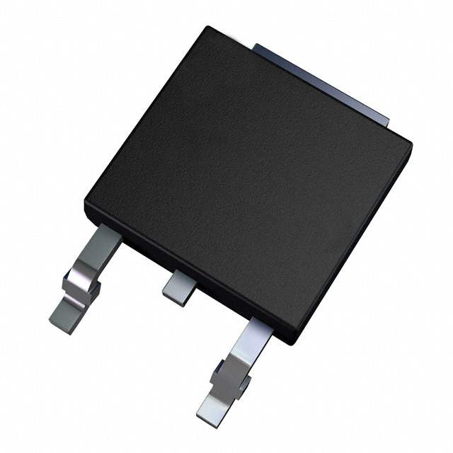
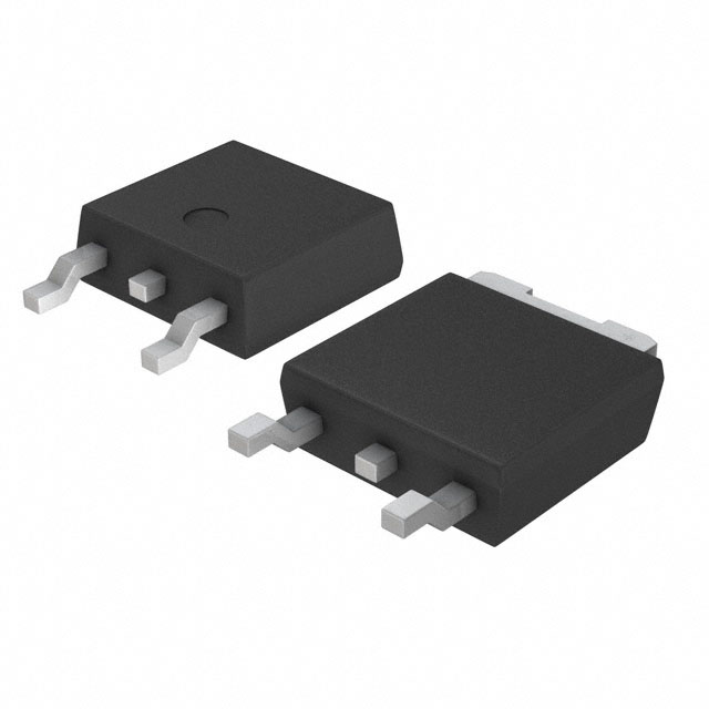
The IRFR3103 is an N-Channel MOSFET manufactured by Infineon Technologies, rated for 400V drain-to-source voltage with 1.7A continuous drain current. The device is packaged in TO-252AA (DPAK) surface mount configuration and is part of the HEXFET® series. The IRFR3103 is classified as obsolete, making identification of equivalent and substitute parts essential for ongoing design support and production continuity. Substitute parts must maintain electrical compatibility across voltage, current, and thermal specifications while accommodating the same or compatible package footprints.
Substiute Parts
Key Parameters
| Parameter | Value | Unit |
|---|---|---|
| Drain-to-Source Voltage (Vdss) | 400 | V |
| Continuous Drain Current (Id) @ 25°C | 1.7 | A |
| Drive Voltage (Max Rds On) | 10 | V |
| Rds On (Max) @ 1A, 10V | 3.6 | Ohm |
| Gate Threshold Voltage (Vgs(th)) @ 250µA | 4 | V |
| Gate Charge (Qg) @ 10V | 12 | nC |
| Maximum Gate Voltage (Vgs) | ±20 | V |
| Input Capacitance (Ciss) @ 25V | 170 | pF |
| Power Dissipation (Max) | 2.5 (Ta), 25 (Tc) | W |
| Package Type | TO-252-3 (DPAK) | - |
| Mounting Type | Surface Mount | - |
| Product Status | Obsolete | - |
Substitute Part Grouping Explanation
Substitution of the IRFR3103 is determined by strict adherence to the following electrical and mechanical parameters:
Critical Matching Parameters:
- Drain-to-Source Voltage (Vdss): Must equal or exceed 400V
- Package Type: Must be TO-252-3 (DPAK) or compatible surface mount equivalent
- FET Type: N-Channel MOSFET technology
- Mounting: Surface Mount
Acceptable Variation Parameters:
- Continuous Drain Current (Id): Substitute must meet or exceed 1.7A at rated conditions
- Rds On (Max): Substitute must not exceed 3.6 Ohm @ 1A, 10V to maintain equivalent switching performance
- Gate Charge (Qg): Lower values acceptable; higher values require circuit evaluation
- Power Dissipation: Substitute must support thermal requirements of the application
- Gate Voltage (Vgs): Substitute must accommodate ±20V or greater
Compliance Considerations:
- RoHS Status: IRFR3103 is RoHS non-compliant; active substitutes should be RoHS3 compliant for new designs
- Moisture Sensitivity Level (MSL): All candidates maintain MSL 1 (Unlimited) or equivalent
The four substitute parts listed below satisfy these criteria with varying performance enhancements suitable for different application requirements.
Parameter Comparison
| Parameter | IRFR3103 | IRFR310TRPBF | AOD3N40 | FDD3N40TM | TN2640K4-G |
|---|---|---|---|---|---|
| Manufacturer | Infineon | Vishay Siliconix | Alpha & Omega | onsemi | Microchip |
| Vdss (V) | 400 | 400 | 400 | 400 | 400 |
| Id @ 25°C (A) | 1.7 | 1.7 | 2.6 | 2.0 | 0.5 |
| Rds On @ 1A, 10V (Ohm) | 3.6 | 3.6 | 3.1 | 3.4 | 5.0 |
| Vgs(th) @ 250µA (V) | 4 | 4 | 4.5 | 5 | 2 |
| Qg @ 10V (nC) | 12 | 12 | 5.1 | 6 | N/A |
| Vgs (Max) (V) | ±20 | ±20 | ±30 | ±30 | ±20 |
| Ciss @ 25V (pF) | 170 | 170 | 225 | 225 | 225 |
| Power Dissipation (W) | 2.5 (Ta), 25 (Tc) | 2.5 (Ta), 25 (Tc) | 50 (Tc) | 30 (Tc) | 2.5 (Ta) |
| Operating Temperature (°C) | Not specified | -55 to 150 | -50 to 150 | -55 to 150 | -55 to 150 |
| Package | TO-252-3 (DPAK) | TO-252-3 (DPAK) | TO-252-3 (DPAK) | TO-252-3 (DPAK) | TO-252-3 (DPAK) |
| Product Status | Obsolete | Active | Active | Active | Active |
| RoHS Status | Non-compliant | ROHS3 Compliant | ROHS3 Compliant | ROHS3 Compliant | ROHS3 Compliant |
Engineering Selection Recommendations
IRFR310TRPBF (Vishay Siliconix)
The IRFR310TRPBF is a direct electrical equivalent to the IRFR3103, matching all critical specifications including Vdss (400V), Id (1.7A), Rds On (3.6 Ohm), and gate charge (12 nC). This part is manufactured by Vishay Siliconix and maintains active product status with ROHS3 compliance. The IRFR310TRPBF is suitable for direct replacement in existing designs without circuit modification. Operating temperature range extends to -55°C to 150°C, providing broader environmental coverage than the obsolete IRFR3103.
AOD3N40 (Alpha & Omega Semiconductor)
The AOD3N40 provides enhanced current capability (2.6A vs. 1.7A) and improved thermal performance (50W Tc vs. 25W Tc) while maintaining 400V Vdss rating. Rds On is reduced to 3.1 Ohm, offering lower conduction losses. Gate charge is significantly lower at 5.1 nC, reducing switching losses and gate drive requirements. This part is suitable for applications requiring higher current density or improved thermal margins. ROHS3 compliance and active status support new design integration.
FDD3N40TM (onsemi UniFET™)
The FDD3N40TM offers moderate current enhancement (2.0A vs. 1.7A) with 30W Tc thermal rating. Rds On (3.4 Ohm) and gate charge (6 nC) provide balanced performance between the IRFR3103 and higher-performance alternatives. The UniFET™ series designation indicates optimized switching characteristics. This part is suitable for applications where modest performance improvement is desired without significant design changes. ROHS3 compliance and active status are confirmed.
TN2640K4-G (Microchip Technology)
The TN2640K4-G is a lower-current alternative (500mA vs. 1.7A) suitable only for applications with reduced current requirements. Rds On is higher at 5.0 Ohm, resulting in increased conduction losses. Gate threshold voltage is significantly lower at 2V, requiring careful gate drive circuit design. This part is not recommended as a direct substitute for the IRFR3103 in standard applications but may serve specialized low-current designs. ROHS3 compliance and active status are confirmed.
Frequently Asked Questions (FAQ)
Q: Can IRFR310TRPBF directly replace IRFR3103 without circuit modification?
A: Yes. The IRFR310TRPBF is electrically identical to the IRFR3103 across all critical parameters: 400V Vdss, 1.7A Id, 3.6 Ohm Rds On, and 12 nC gate charge. Both use TO-252-3 (DPAK) packaging. The primary difference is product status (Active vs. Obsolete) and RoHS compliance. No circuit changes are required.
Q: What is the advantage of AOD3N40 over IRFR310TRPBF?
A: The AOD3N40 provides higher continuous drain current (2.6A vs. 1.7A), lower on-resistance (3.1 Ohm vs. 3.6 Ohm), and significantly lower gate charge (5.1 nC vs. 12 nC). These improvements reduce conduction losses, switching losses, and gate drive power. Thermal capability increases to 50W Tc. Selection depends on application current requirements and thermal constraints.
Q: Are all substitute parts in the same package?
A: Yes. All substitute parts use TO-252-3 (DPAK) surface mount packaging, identical to the IRFR3103. PCB footprints are compatible without modification.
Q: Which substitute part is recommended for new designs?
A: IRFR310TRPBF or AOD3N40 are recommended for new designs. Both are active products with ROHS3 compliance. IRFR310TRPBF provides direct equivalence; AOD3N40 offers performance enhancement. FDD3N40TM is also acceptable. TN2640K4-G is not recommended unless current requirements are below 500mA.
Q: What is the significance of gate charge (Qg) differences?
A: Gate charge determines the energy required to switch the MOSFET on and off. Lower gate charge (AOD3N40 at 5.1 nC, FDD3N40TM at 6 nC) reduces gate drive circuit power dissipation and enables faster switching. Higher gate charge (IRFR3103 and IRFR310TRPBF at 12 nC) requires more gate drive energy but may be acceptable in applications with adequate drive capability.
Q: Can TN2640K4-G be used in place of IRFR3103?
A: No. The TN2640K4-G is rated for only 500mA continuous drain current, significantly below the IRFR3103 specification of 1.7A. Use of this part in applications requiring 1.7A operation will result in device failure. The TN2640K4-G is suitable only for specialized low-current applications.
Q: What does RoHS3 compliance mean for substitute selection?
A: RoHS3 compliance indicates the part meets Restriction of Hazardous Substances Directive requirements, restricting lead, cadmium, mercury, and other hazardous materials. The IRFR3103 is RoHS non-compliant. All active substitute parts (IRFR310TRPBF, AOD3N40, FDD3N40TM, TN2640K4-G) are ROHS3 compliant, making them suitable for new designs and applications subject to environmental regulations.
Q: How do operating temperature ranges affect substitution?
A: The IRFR3103 does not specify an operating temperature range. All substitute parts specify -55°C to -50°C minimum and 150°C maximum junction temperature, providing defined thermal operating windows. This specification clarity supports reliability analysis and thermal design validation for new applications.
Q: Is Rds On variation significant between substitutes?
A: Yes. Rds On variation directly affects conduction losses and heat dissipation. IRFR3103 and IRFR310TRPBF specify 3.6 Ohm; AOD3N40 specifies 3.1 Ohm (lower loss); FDD3N40TM specifies 3.4 Ohm; TN2640K4-G specifies 5.0 Ohm (higher loss). In high-current or high-frequency applications, lower Rds On reduces thermal stress and improves efficiency.
Alternative Parts

SJ6012L2TP
Littelfuse Inc.
6 Alternative Parts

JMK107BBJ476MA-RE
Taiyo Yuden
10 Alternative Parts

GMK107BBJ475MA-T
Taiyo Yuden
5 Alternative Parts
SJ6020N2ARP
Littelfuse Inc.
3 Alternative Parts
SJ6025R2ATP
Littelfuse Inc.
4 Alternative Parts

2474-05L
API Delevan Inc.
1 Alternative Parts

4590R-684K
API Delevan Inc.
1 Alternative Parts

CM6560R-334
API Delevan Inc.
1 Alternative Parts

CM6460-104
API Delevan Inc.
1 Alternative Parts

5526-12
API Delevan Inc.
1 Alternative Parts