


Request Quote
(Ships tomorrow)
IRFR2407PBF N-Channel MOSFET Equivalent & Substitute Parts
Part Overview
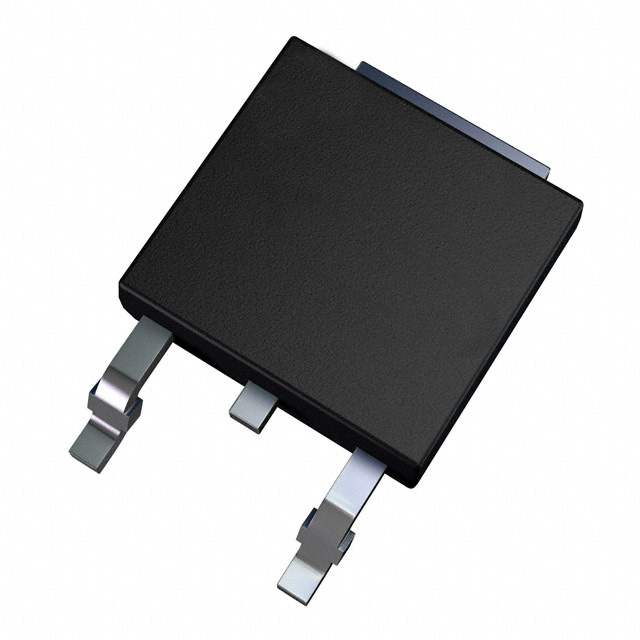
The IRFR2407PBF is an N-Channel MOSFET manufactured by Infineon Technologies, rated for 75V drain-to-source voltage with 42A continuous drain current at 25°C. This device is packaged in TO-252-3 (DPAK) surface mount configuration and is part of the HEXFET® series. The part is currently discontinued at DiGi Electronics, necessitating identification of functionally equivalent alternatives that maintain electrical and mechanical compatibility for existing designs.
Substiute Parts
Key Parameters
| Parameter | Value | Unit |
|---|---|---|
| Drain-to-Source Voltage (Vdss) | 75 | V |
| Continuous Drain Current (Id) @ 25°C | 42 | A (Tc) |
| On-State Resistance (Rds On) @ 25A, 10V | 26 | mOhm |
| Gate Threshold Voltage (Vgs(th)) @ 250µA | 4 | V |
| Gate Charge (Qg) @ 10V | 110 | nC |
| Power Dissipation (Max) | 110 | W (Tc) |
| Operating Temperature Range | -55 to 175 | °C (TJ) |
| Package Type | TO-252-3 (DPAK) | Surface Mount |
| Maximum Gate Voltage (Vgs) | ±20 | V |
| Input Capacitance (Ciss) @ 25V | 2400 | pF |
Substitute Part Grouping Explanation
Substitution of the IRFR2407PBF is determined by the following critical electrical and mechanical parameters:
Primary Substitution Criteria:
- Drain-to-Source Voltage (Vdss): Must equal or exceed 75V
- Continuous Drain Current (Id): Must equal or exceed 42A at 25°C
- Package Type: Must be TO-252-3 (DPAK) surface mount
- Operating Temperature Range: Must support -55°C to 175°C
- Gate Voltage Rating (Vgs): Must support ±20V or greater
Secondary Compatibility Parameters:
- On-State Resistance (Rds On): Lower values indicate improved performance
- Gate Charge (Qg): Lower values reduce switching losses
- Power Dissipation: Must support thermal requirements of the application
Substitute parts are grouped into two categories:
Category A - Direct Voltage/Current Equivalents (75V, ≥42A): Parts maintaining the original 75V rating with equal or higher current ratings in DPAK packaging.
Category B - Higher Voltage Alternatives (100V, ≥30A): Parts with elevated voltage ratings (100V) that provide design margin while maintaining compatible current and package specifications. These are suitable for applications where voltage headroom is beneficial.
Parameter Comparison
| Part Number | Manufacturer | Vdss (V) | Id @ 25°C (A) | Rds On (mOhm) | Vgs(th) (V) | Qg (nC) | Power Diss. (W) | Package | Status |
|---|---|---|---|---|---|---|---|---|---|
| IRFR2407PBF | Infineon | 75 | 42 | 26 @ 25A, 10V | 4 @ 250µA | 110 @ 10V | 110 | TO-252-3 (DPAK) | Discontinued |
| BUK9226-75A,118 | Nexperia | 75 | 45 | 24.6 @ 25A, 10V | 2 @ 1mA | N/A | 114 | TO-252-3 (DPAK) | Obsolete |
| STD30NF06LT4 | STMicroelectronics | 60 | 35 | 28 @ 18A, 10V | 2.5 @ 250µA | 31 @ 5V | 70 | TO-252-3 (DPAK) | Active |
| IPD35N10S3L26ATMA1 | Infineon | 100 | 35 | 24 @ 35A, 10V | 2.4 @ 39µA | 39 @ 10V | 71 | TO-252-3 (DPAK) | Active |
| IPD30N10S3L34ATMA1 | Infineon | 100 | 30 | 31 @ 30A, 10V | 2.4 @ 29µA | 31 @ 10V | 57 | TO-252-3 (DPAK) | Active |
| STD25NF10LT4 | STMicroelectronics | 100 | 25 | 35 @ 12.5A, 10V | 2.5 @ 250µA | 52 @ 5V | 100 | TO-252-3 (DPAK) | Active |
| STD25NF10T4 | STMicroelectronics | 100 | 25 | 38 @ 12.5A, 10V | 4 @ 250µA | 55 @ 10V | 100 | TO-252-3 (DPAK) | Active |
| STD26NF10 | STMicroelectronics | 100 | 25 | 38 @ 12.5A, 10V | 4 @ 250µA | 55 @ 10V | 100 | TO-252-3 (DPAK) | Active |
| FDD10AN06A0 | onsemi | 60 | 50 | 10.5 @ 50A, 10V | 4 @ 250µA | 37 @ 10V | 135 | TO-252-3 (DPAK) | Active |
| HUF75329D3ST | onsemi | 55 | 20 | 26 @ 20A, 10V | 4 @ 250µA | 65 @ 20V | 128 | TO-252-3 (DPAK) | Active |
| IRFU4105ZTRL | Vishay Siliconix | 55 | 30 | 24.5 @ 18A, 10V | 4 @ 250µA | 27 @ 10V | 48 | TO-251-3 (Through Hole) | Active |
Engineering Selection Recommendations
Recommended Primary Substitutes (Active Status, Full Compatibility):
IPD35N10S3L26ATMA1 (Infineon OptiMOS™ series) is the preferred substitute. This part maintains the same manufacturer ecosystem as the original IRFR2407PBF, operates at 100V/35A with improved on-state resistance (24 mOhm), and is in active production status. The elevated voltage rating provides design margin while the current rating of 35A accommodates applications requiring up to 42A through thermal management or duty cycle considerations. RoHS3 compliance and identical package configuration ensure direct PCB compatibility.
IPD30N10S3L34ATMA1 (Infineon OptiMOS™ series) serves as an alternative for applications with lower current requirements (30A continuous). This part offers superior gate charge characteristics (31 nC) and lower power dissipation (57W), beneficial for high-frequency switching applications. Active production status and RoHS3 compliance are confirmed.
STD30NF06LT4 (STMicroelectronics STripFET™ series) provides a 60V/35A alternative with active production status. This part matches the original voltage rating and exceeds current requirements. On-state resistance of 28 mOhm and gate charge of 31 nC at 5V indicate efficient switching characteristics. RoHS3 compliance and DPAK packaging ensure compatibility.
Secondary Substitutes (Active Status, Current Derating Required):
FDD10AN06A0 (onsemi PowerTrench® series) operates at 60V with 50A continuous current rating, exceeding the original current specification. The exceptionally low on-state resistance (10.5 mOhm) and high power dissipation rating (135W) make this suitable for high-current, low-loss applications. Active production status and RoHS3 compliance are confirmed. Package is TO-252AA (DPAK equivalent).
Not Recommended:
BUK9226-75A,118 (Nexperia TrenchMOS™) maintains 75V/45A specifications with improved on-state resistance (24.6 mOhm). However, this part is marked as Obsolete, making long-term supply uncertain. Use only if existing inventory is available and supply chain continuity is not a concern.
STD25NF10LT4, STD25NF10T4, STD26NF10 (STMicroelectronics STripFET™ II series) operate at 100V but are limited to 25A continuous current, significantly below the 42A requirement of the original part. These are unsuitable for direct replacement in applications requiring full current capacity.
IRFU4105ZTRL (Vishay Siliconix) is a through-hole package device (TO-251-3), incompatible with surface mount PCB layouts designed for DPAK. Additionally, RoHS non-compliance status and 55V/30A ratings make this unsuitable for direct substitution.
HUF75329D3ST (onsemi UltraFET™) operates at 55V with only 20A continuous current, insufficient for the original 42A specification.
Frequently Asked Questions (FAQ)
Q1: Can I use a 100V-rated MOSFET in place of the 75V IRFR2407PBF?
A: Yes. The 100V-rated substitutes (IPD35N10S3L26ATMA1, IPD30N10S3L34ATMA1, STD25NF10LT4, STD25NF10T4, STD26NF10) are electrically compatible. Higher voltage ratings provide additional design margin and do not degrade performance in 75V applications. However, verify that the continuous drain current rating meets your application requirements. IPD35N10S3L26ATMA1 (35A) is preferred over the 25A-rated STMicroelectronics parts for applications requiring the full 42A capacity.
Q2: What is the significance of on-state resistance (Rds On) when selecting a substitute?
A: Rds On directly affects power dissipation and heat generation. Lower Rds On values reduce I²R losses during conduction. The original IRFR2407PBF specifies 26 mOhm at 25A/10V. Substitutes with lower Rds On (such as FDD10AN06A0 at 10.5 mOhm or IPD35N10S3L26ATMA1 at 24 mOhm) improve efficiency and reduce thermal management requirements. Higher Rds On values increase power dissipation and may require enhanced cooling.
Q3: Are all substitute parts in the same package?
A: Most substitutes use TO-252-3 (DPAK) surface mount packaging, directly compatible with the original IRFR2407PBF PCB layout. Exception: IRFU4105ZTRL uses TO-251-3 (through-hole IPak), which is mechanically and electrically incompatible with DPAK footprints and is not recommended for direct substitution.
Q4: What does "Active" versus "Discontinued" or "Obsolete" status mean for component selection?
A: Active status indicates the manufacturer currently produces the part and maintains supply chain availability. Discontinued or Obsolete status signals that production has ended, creating supply risk. For new designs or long-term production, select only Active-status parts. The original IRFR2407PBF is Discontinued; all recommended substitutes carry Active status to ensure supply continuity.
Q5: Why do some substitutes have lower current ratings than the original 42A specification?
A: STMicroelectronics STripFET™ II parts (STD25NF10LT4, STD25NF10T4, STD26NF10) are rated for 25A continuous current, below the original 42A. These parts are unsuitable for direct replacement in applications requiring full current capacity. Use only if your application's actual current draw is ≤25A, or if you can implement current derating through design modifications.
Q6: What is gate charge (Qg) and why does it matter?
A: Gate charge represents the total charge required to switch the MOSFET from off to on state. Lower Qg values reduce switching losses and enable faster switching speeds, beneficial for high-frequency applications. The original IRFR2407PBF specifies 110 nC at 10V. Substitutes with lower Qg (IPD30N10S3L34ATMA1 at 31 nC, STD30NF06LT4 at 31 nC) improve switching efficiency. Higher Qg values increase switching losses and heat generation.
Q7: Are all recommended substitutes RoHS3 compliant?
A: Yes. All Active-status recommended substitutes (IPD35N10S3L26ATMA1, IPD30N10S3L34ATMA1, STD30NF06LT4, FDD10AN06A0) carry RoHS3 Compliant status. The original IRFR2407PBF is also RoHS3 Compliant. This ensures compatibility with environmental regulations and procurement requirements.
Q8: Can I use FDD10AN06A0 if my application requires 42A continuous current?
A: FDD10AN06A0 is rated for 50A continuous current at 25°C (Tc), exceeding the 42A requirement. However, verify that your PCB thermal design can dissipate the power generated. FDD10AN06A0 has a power dissipation rating of 135W (Tc), higher than the original 110W. Ensure adequate copper area, thermal vias, and heat sinking are implemented to maintain junction temperature within the -55°C to 175°C operating range.
Q9: What is the difference between Tc (case temperature) and Ta (ambient temperature) current ratings?
A: Tc (case temperature) ratings assume the device case is maintained at 25°C through active cooling or thermal management. Ta (ambient temperature) ratings assume only passive cooling at 25°C ambient. FDD10AN06A0 specifies 11A (Ta) and 50A (Tc), indicating that 50A is achievable only with case temperature control. For applications without active cooling, derate the current accordingly based on thermal design.
Q10: Should I test substitute parts before full production deployment?
A: Verification of electrical performance, thermal behavior, and PCB compatibility is a standard engineering practice. Conduct functional testing, thermal profiling, and reliability assessment on prototype units before committing to production quantities. This ensures the substitute meets all application requirements and design margins.
Alternative Parts

SJ6012L2TP
Littelfuse Inc.
6 Alternative Parts

JMK107BBJ476MA-RE
Taiyo Yuden
10 Alternative Parts

GMK107BBJ475MA-T
Taiyo Yuden
5 Alternative Parts
SJ6020N2ARP
Littelfuse Inc.
3 Alternative Parts
SJ6025R2ATP
Littelfuse Inc.
4 Alternative Parts

2474-05L
API Delevan Inc.
1 Alternative Parts

4590R-684K
API Delevan Inc.
1 Alternative Parts

CM6560R-334
API Delevan Inc.
1 Alternative Parts

CM6460-104
API Delevan Inc.
1 Alternative Parts

5526-12
API Delevan Inc.
1 Alternative Parts