


Request Quote
(Ships tomorrow)
IRFP9140 P-Channel MOSFET Equivalent & Substitute Parts
Part Overview
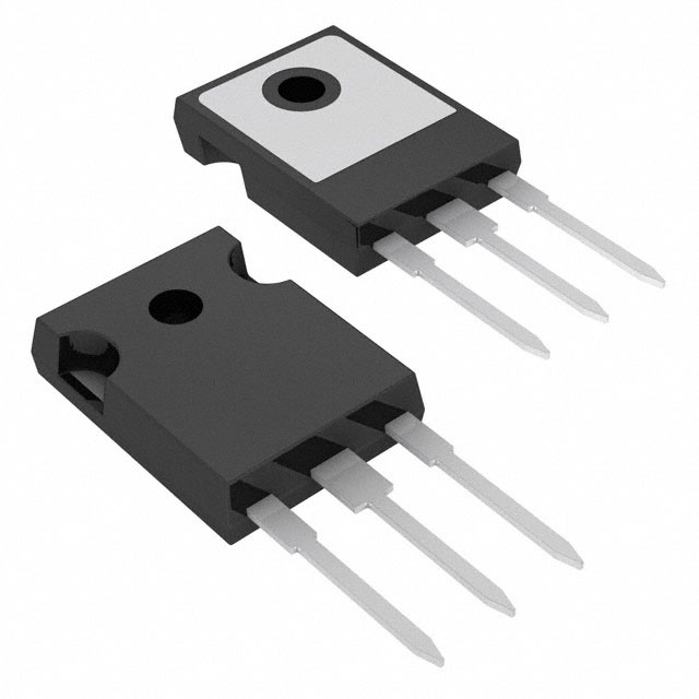
The IRFP9140 is a P-Channel Metal Oxide Semiconductor Field Effect Transistor (MOSFET) rated for 100V drain-to-source voltage with 21A continuous drain current at 25°C. Housed in a TO-247AC through-hole package, this device delivers 180W maximum power dissipation and operates across the temperature range of -55°C to 175°C (junction temperature).
The IRFP9140 is classified as obsolete. Locating equivalent and substitute parts is necessary to support ongoing production requirements, field repairs, and system maintenance where this component remains in active use. Substitute parts must maintain electrical and mechanical compatibility within the specified parameter tolerances.
Substiute Parts
Key Parameters
| Parameter | Value | Unit |
|---|---|---|
| FET Type | P-Channel | — |
| Drain to Source Voltage (Vdss) | 100 | V |
| Current - Continuous Drain (Id) @ 25°C | 21 | A (Tc) |
| Drive Voltage (Max Rds On) | 10 | V |
| Rds On (Max) @ Id, Vgs | 200 | mOhm @ 13A, 10V |
| Vgs(th) (Max) @ Id | 4 | V @ 250µA |
| Gate Charge (Qg) (Max) @ Vgs | 61 | nC @ 10V |
| Vgs (Max) | ±20 | V |
| Input Capacitance (Ciss) (Max) @ Vds | 1400 | pF @ 25V |
| Power Dissipation (Max) | 180 | W (Tc) |
| Operating Temperature | -55 to 175 | °C (TJ) |
| Mounting Type | Through Hole | — |
| Package / Case | TO-247-3 | — |
Substitute Part Grouping Explanation
Substitute parts for the IRFP9140 are classified based on strict electrical and mechanical parameter alignment. The substitution logic is determined by the following critical parameters:
Electrical Compatibility Criteria:
- FET Type: P-Channel topology must be maintained
- Drain to Source Voltage (Vdss): 100V rating is the baseline requirement
- Continuous Drain Current (Id): Minimum 21A at 25°C
- Gate Threshold Voltage (Vgs(th)): 4V @ 250µA
- Maximum Gate Voltage (Vgs): ±20V
- On-State Resistance (Rds On): 200mOhm @ 13A, 10V or lower
- Operating Temperature Range: -55°C to 175°C (TJ)
Mechanical Compatibility Criteria:
- Mounting Type: Through Hole
- Package / Case: TO-247-3 (TO-247AC)
Substitute parts are grouped into two categories:
Category 1: Direct Manufacturer Equivalents Parts manufactured by the original supplier (Vishay Siliconix) with identical electrical specifications and active product status. These parts carry the same base product number with different packaging or lead finish designations.
Category 2: Manufacturer-Recommended Alternatives Parts from alternative manufacturers (Infineon Technologies) that meet or exceed the electrical performance requirements while maintaining mechanical compatibility. These parts may exhibit improved performance characteristics such as lower on-state resistance or higher current ratings.
Parameter Comparison
| Parameter | IRFP9140 (Main) | IRFP9140PBF (Direct) | IRFP9140NPBF (Alternative) | Unit |
|---|---|---|---|---|
| Manufacturer | Vishay Siliconix | Vishay Siliconix | Infineon Technologies | — |
| Product Status | Obsolete | Active | Active | — |
| FET Type | P-Channel | P-Channel | P-Channel | — |
| Vdss | 100 | 100 | 100 | V |
| Id @ 25°C | 21 | 21 | 23 | A (Tc) |
| Rds On (Max) @ 13A, 10V | 200 | 200 | 117 | mOhm |
| Vgs(th) (Max) @ 250µA | 4 | 4 | 4 | V |
| Gate Charge (Qg) @ 10V | 61 | 61 | 97 | nC |
| Vgs (Max) | ±20 | ±20 | ±20 | V |
| Ciss (Max) @ 25V | 1400 | 1400 | 1300 | pF |
| Power Dissipation (Max) | 180 | 180 | 140 | W (Tc) |
| Operating Temperature | -55 to 175 | -55 to 175 | -55 to 175 | °C (TJ) |
| Package / Case | TO-247-3 | TO-247-3 | TO-247-3 | — |
| RoHS Status | Non-compliant | ROHS3 Compliant | ROHS3 Compliant | — |
| REACH Status | Unaffected | Unaffected | Unaffected | — |
Engineering Selection Recommendations
IRFP9140PBF (Direct Manufacturer Equivalent)
The IRFP9140PBF is manufactured by Vishay Siliconix and maintains identical electrical specifications to the obsolete IRFP9140. This part is classified as Active product status, ensuring continued availability and supply chain support. The IRFP9140PBF carries ROHS3 compliance certification, meeting current environmental and regulatory requirements. This substitute is suitable for direct replacement in applications where the original IRFP9140 specifications are required and regulatory compliance is mandatory.
IRFP9140NPBF (Manufacturer-Recommended Alternative)
The IRFP9140NPBF is manufactured by Infineon Technologies under the HEXFET® series designation. This part exceeds the electrical performance of the original IRFP9140 in the following aspects: continuous drain current of 23A (versus 21A), and significantly lower on-state resistance of 117mOhm at 13A, 10V (versus 200mOhm). The IRFP9140NPBF is classified as Active product status with ROHS3 compliance certification. The maximum power dissipation rating of 140W is lower than the original 180W specification; this parameter must be evaluated against the thermal requirements of the target application. The IRFP9140NPBF is suitable for applications where improved electrical performance and regulatory compliance are priorities, provided that the 140W power dissipation ceiling does not constrain thermal design.
Both substitute parts maintain mechanical compatibility through identical TO-247-3 through-hole packaging and are qualified for the full operating temperature range of -55°C to 175°C (junction temperature).
Frequently Asked Questions (FAQ)
Q: Can the IRFP9140PBF be used as a direct replacement for the obsolete IRFP9140?
A: Yes. The IRFP9140PBF is manufactured by the same supplier (Vishay Siliconix) and maintains identical electrical specifications including Vdss (100V), Id (21A), Rds On (200mOhm @ 13A, 10V), and operating temperature range (-55°C to 175°C). Both parts use the TO-247-3 package. The primary difference is product status (Active versus Obsolete) and RoHS compliance (ROHS3 Compliant versus Non-compliant). No circuit modifications are required.
Q: What are the key differences between the IRFP9140PBF and IRFP9140NPBF?
A: The IRFP9140PBF and IRFP9140NPBF differ in manufacturer, on-state resistance, continuous drain current, and power dissipation rating. The IRFP9140NPBF (Infineon) provides lower on-state resistance (117mOhm versus 200mOhm), higher continuous drain current (23A versus 21A), but lower maximum power dissipation (140W versus 180W). Both maintain the same Vdss (100V), Vgs(th) (4V @ 250µA), and operating temperature range. Gate charge is higher in the IRFP9140NPBF (97nC versus 61nC @ 10V).
Q: Is the IRFP9140NPBF suitable for all applications using the original IRFP9140?
A: The IRFP9140NPBF is suitable for most applications, with one critical consideration: the maximum power dissipation rating is 140W compared to the original 180W. Applications requiring sustained power dissipation above 140W must retain the original IRFP9140 or IRFP9140PBF. The improved on-state resistance (117mOhm) of the IRFP9140NPBF typically results in lower power dissipation during normal operation, making it compatible with most designs. Thermal analysis of the specific application is required to confirm compatibility.
Q: Are both substitute parts available in the same package as the original IRFP9140?
A: Yes. Both the IRFP9140PBF and IRFP9140NPBF are housed in the TO-247-3 (TO-247AC) through-hole package, identical to the original IRFP9140. Pin configuration and mechanical dimensions are compatible with existing PCB layouts and heat sink mounting arrangements.
Q: What is the significance of the RoHS compliance difference?
A: The original IRFP9140 is RoHS non-compliant, while both substitute parts (IRFP9140PBF and IRFP9140NPBF) are ROHS3 compliant. RoHS3 compliance indicates that the parts meet current environmental regulations restricting hazardous substances. For applications subject to regulatory requirements or customer specifications mandating RoHS compliance, the substitute parts are necessary. Both substitute parts carry identical REACH Unaffected status.
Q: How do the gate charge specifications affect circuit design?
A: Gate charge (Qg) determines the energy required to switch the MOSFET on and off. The IRFP9140 and IRFP9140PBF both specify 61nC @ 10V, while the IRFP9140NPBF specifies 97nC @ 10V. Higher gate charge requires greater driver current or longer switching times. For applications with marginal gate driver capability, the lower gate charge of the IRFP9140PBF may be preferable. For most modern gate driver circuits, the 97nC specification of the IRFP9140NPBF is within acceptable operating range.
Q: Can these parts be used interchangeably in existing designs without PCB modification?
A: Yes. All three parts (IRFP9140, IRFP9140PBF, IRFP9140NPBF) use the TO-247-3 package with identical pin assignments and mechanical dimensions. No PCB layout changes are required. However, thermal design must be re-evaluated for the IRFP9140NPBF due to its lower maximum power dissipation rating (140W).
Alternative Parts

SJ6012L2TP
Littelfuse Inc.
6 Alternative Parts

JMK107BBJ476MA-RE
Taiyo Yuden
10 Alternative Parts

GMK107BBJ475MA-T
Taiyo Yuden
5 Alternative Parts
SJ6020N2ARP
Littelfuse Inc.
3 Alternative Parts
SJ6025R2ATP
Littelfuse Inc.
4 Alternative Parts

2474-05L
API Delevan Inc.
1 Alternative Parts

4590R-684K
API Delevan Inc.
1 Alternative Parts

CM6560R-334
API Delevan Inc.
1 Alternative Parts

CM6460-104
API Delevan Inc.
1 Alternative Parts

5526-12
API Delevan Inc.
1 Alternative Parts