


Request Quote
(Ships tomorrow)
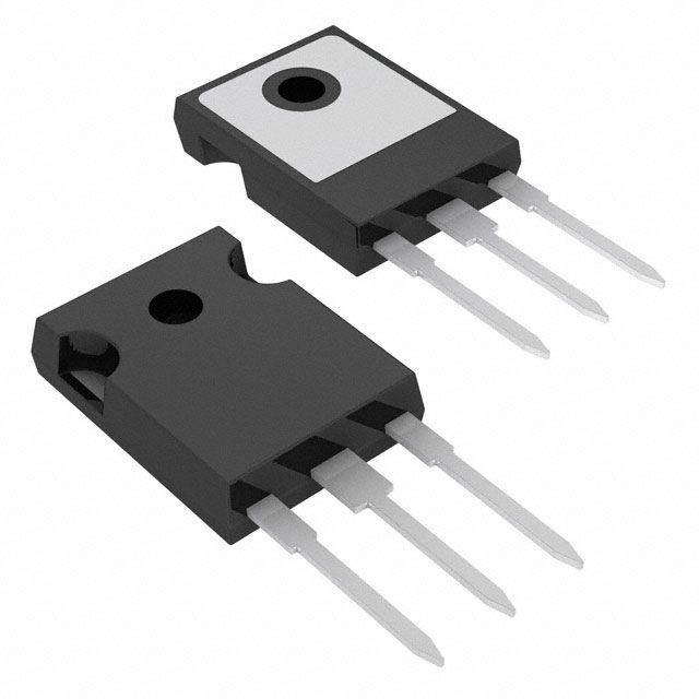
IRFP448PBF N-Channel 500V 11A MOSFET Equivalent & Substitute Parts
Part Overview
The IRFP448PBF is an N-Channel Metal Oxide Semiconductor Field Effect Transistor (MOSFET) manufactured by Vishay Siliconix, rated for 500V drain-to-source voltage with 11A continuous drain current at 25°C. The device is packaged in a TO-247-3 through-hole configuration and is designed for high-voltage switching applications requiring 180W power dissipation capability. The IRFP448PBF maintains Active product status with full RoHS3 compliance and unlimited moisture sensitivity rating (MSL 1). Equivalent and substitute parts are identified based on matching or exceeding critical electrical parameters including voltage rating, current capacity, on-resistance characteristics, and thermal performance within the same package family.
Substiute Parts
Key Parameters
| Parameter | Value | Unit |
|---|---|---|
| Drain to Source Voltage (Vdss) | 500 | V |
| Continuous Drain Current (Id) @ 25°C | 11 | A (Tc) |
| On-Resistance (Rds On Max) @ Id, Vgs | 600 mOhm @ 6.6A, 10V | mOhm |
| Gate Threshold Voltage (Vgs(th) Max) @ Id | 4 | V @ 250µA |
| Gate Charge (Qg Max) @ Vgs | 84 | nC @ 10V |
| Maximum Gate Voltage (Vgs Max) | ±20 | V |
| Input Capacitance (Ciss Max) @ Vds | 1900 | pF @ 25V |
| Power Dissipation (Max) | 180 | W (Tc) |
| Operating Temperature Range | -55 to 150 | °C (TJ) |
| Package Type | TO-247-3 | Through Hole |
| RoHS Status | ROHS3 Compliant | — |
Substitute Part Grouping Explanation
Substitute parts for the IRFP448PBF are qualified based on the following criteria:
Voltage Rating Compatibility: All substitute parts must maintain the 500V Vdss rating to ensure safe operation in the same circuit topology without exceeding voltage stress limits.
Package Compatibility: All substitutes are mounted in TO-247-3 or equivalent TO-247 through-hole packages, ensuring mechanical and thermal interface compatibility with existing PCB layouts and heatsink assemblies.
Current and Thermal Performance: Substitute parts are evaluated on continuous drain current capacity and power dissipation ratings. Parts with equal or higher current ratings and thermal performance are considered direct substitutes. Parts with lower current ratings are qualified as derating substitutes for applications with reduced current demands.
On-Resistance Characteristics: Rds On values determine switching losses and thermal performance. Lower Rds On values indicate improved efficiency and reduced heat generation at equivalent current levels.
Gate Drive Requirements: Gate threshold voltage (Vgs(th)) and gate charge (Qg) parameters determine compatibility with existing gate driver circuits. Parts with similar gate drive characteristics ensure consistent switching behavior without circuit redesign.
Compliance and Certification: All substitute parts maintain RoHS3 compliance, MSL 1 rating, and EAR99 export classification, ensuring regulatory and supply chain compatibility.
Parameter Comparison
| Parameter | IRFP448PBF (Vishay) | STW14NK50Z (STMicroelectronics) | IXTH6N50D2 (IXYS) |
|---|---|---|---|
| Manufacturer | Vishay Siliconix | STMicroelectronics | IXYS |
| FET Type | N-Channel | N-Channel | N-Channel |
| Drain to Source Voltage (Vdss) | 500 V | 500 V | 500 V |
| Continuous Drain Current (Id) @ 25°C | 11 A (Tc) | 14 A (Tc) | 6 A (Tc) |
| Rds On (Max) @ Id, Vgs | 600 mOhm @ 6.6A, 10V | 380 mOhm @ 6A, 10V | 500 mOhm @ 3A, 0V |
| Vgs(th) (Max) @ Id | 4 V @ 250µA | 4.5 V @ 100µA | Not specified |
| Gate Charge (Qg Max) @ Vgs | 84 nC @ 10V | 92 nC @ 10V | 96 nC @ 5V |
| Vgs (Max) | ±20 V | ±30 V | ±20 V |
| Input Capacitance (Ciss Max) @ Vds | 1900 pF @ 25V | 2000 pF @ 25V | 2800 pF @ 25V |
| Power Dissipation (Max) | 180 W (Tc) | 150 W (Tc) | 300 W (Tc) |
| Operating Temperature | -55 to 150 °C (TJ) | -55 to 150 °C (TJ) | -55 to 150 °C (TJ) |
| Package / Case | TO-247-3 | TO-247-3 | TO-247-3 |
| RoHS Status | ROHS3 Compliant | ROHS3 Compliant | ROHS3 Compliant |
| MSL Rating | 1 (Unlimited) | 1 (Unlimited) | 1 (Unlimited) |
Engineering Selection Recommendations
STW14NK50Z (STMicroelectronics) - Primary Substitute
The STW14NK50Z is qualified as a direct substitute for the IRFP448PBF in applications requiring equal or higher current capacity. This device exceeds the IRFP448PBF in continuous drain current (14A vs. 11A) and demonstrates superior on-resistance performance (380 mOhm vs. 600 mOhm at comparable conditions), resulting in reduced switching losses and improved thermal efficiency. The STW14NK50Z maintains identical voltage rating (500V), operating temperature range (-55 to 150°C), and package configuration (TO-247-3). Gate charge characteristics (92 nC @ 10V) are comparable to the IRFP448PBF (84 nC @ 10V), ensuring compatible gate driver operation. The device carries full RoHS3 compliance and MSL 1 rating. The STW14NK50Z is suitable for direct pin-for-pin replacement in existing designs without circuit modification.
IXTH6N50D2 (IXYS) - Derating Substitute
The IXTH6N50D2 is qualified as a substitute for applications where continuous drain current requirements are reduced to 6A or below. This device maintains the 500V voltage rating and TO-247-3 package compatibility. The IXTH6N50D2 features lower on-resistance (500 mOhm @ 3A, 0V) compared to the IRFP448PBF, but operates as a depletion-mode device with different gate drive characteristics. The higher input capacitance (2800 pF vs. 1900 pF) and higher power dissipation rating (300W vs. 180W) indicate different thermal and switching performance profiles. The IXTH6N50D2 is suitable for replacement only in applications with reduced current demands and where gate drive circuit compatibility with depletion-mode operation is confirmed. Full RoHS3 compliance and MSL 1 rating are maintained.
Frequently Asked Questions (FAQ)
Q: Can the STW14NK50Z replace the IRFP448PBF in all applications?
A: The STW14NK50Z is a direct substitute for applications operating at or below 11A continuous drain current. The superior current rating (14A) and lower on-resistance (380 mOhm) provide improved performance margins. No circuit modification is required for pin-for-pin replacement in TO-247-3 mounted designs. Verify gate driver compatibility based on gate charge specifications (92 nC @ 10V for STW14NK50Z vs. 84 nC @ 10V for IRFP448PBF).
Q: Is the IXTH6N50D2 suitable as a direct replacement?
A: The IXTH6N50D2 is not a direct replacement for applications requiring 11A continuous current. This device is rated for 6A maximum continuous drain current and operates as a depletion-mode MOSFET, requiring different gate drive circuit design. The IXTH6N50D2 is qualified only for applications with reduced current demands (6A or below) and where depletion-mode operation is compatible with the existing gate driver topology.
Q: What are the key differences in on-resistance between these devices?
A: The IRFP448PBF exhibits 600 mOhm on-resistance at 6.6A and 10V gate voltage. The STW14NK50Z demonstrates 380 mOhm at 6A and 10V, representing a 37% reduction in on-resistance and corresponding reduction in conduction losses. The IXTH6N50D2 shows 500 mOhm at 3A and 0V gate voltage, reflecting depletion-mode operation characteristics. Lower on-resistance values reduce power dissipation and thermal stress in high-frequency switching applications.
Q: Are all substitute parts compatible with existing PCB layouts?
A: Yes. All substitute parts (STW14NK50Z and IXTH6N50D2) are packaged in TO-247-3 through-hole configuration, ensuring mechanical and thermal interface compatibility with existing PCB layouts, heatsink assemblies, and mounting hardware. No PCB redesign is required for package compatibility.
Q: What compliance certifications apply to all parts?
A: The IRFP448PBF, STW14NK50Z, and IXTH6N50D2 all maintain RoHS3 compliance, MSL 1 (unlimited moisture sensitivity) rating, and EAR99 export classification. All parts are classified under HTSUS code 8541.29.0095. These certifications ensure regulatory compliance and supply chain compatibility across all three devices.
Q: How do gate charge specifications affect circuit design?
A: Gate charge (Qg) determines the energy required to switch the device and influences gate driver selection. The IRFP448PBF requires 84 nC @ 10V, while the STW14NK50Z requires 92 nC @ 10V. The IXTH6N50D2 requires 96 nC @ 5V. Higher gate charge values increase switching time and power dissipation in the gate driver circuit. Existing gate drivers rated for 84 nC will operate within acceptable margins with the STW14NK50Z (92 nC). The IXTH6N50D2 depletion-mode operation requires gate driver circuit verification.
Q: What is the significance of input capacitance differences?
A: Input capacitance (Ciss) affects gate drive circuit impedance and switching speed. The IRFP448PBF exhibits 1900 pF @ 25V, the STW14NK50Z exhibits 2000 pF @ 25V, and the IXTH6N50D2 exhibits 2800 pF @ 25V. Higher input capacitance increases gate charge requirements and may extend switching transitions. The STW14NK50Z (2000 pF) is nearly equivalent to the IRFP448PBF (1900 pF), ensuring minimal impact on gate driver performance. The IXTH6N50D2 (2800 pF) represents a 47% increase and requires gate driver verification.
Alternative Parts

SJ6012L2TP
Littelfuse Inc.
6 Alternative Parts

JMK107BBJ476MA-RE
Taiyo Yuden
10 Alternative Parts

GMK107BBJ475MA-T
Taiyo Yuden
5 Alternative Parts
SJ6020N2ARP
Littelfuse Inc.
3 Alternative Parts
SJ6025R2ATP
Littelfuse Inc.
4 Alternative Parts

2474-05L
API Delevan Inc.
1 Alternative Parts

4590R-684K
API Delevan Inc.
1 Alternative Parts

CM6560R-334
API Delevan Inc.
1 Alternative Parts

CM6460-104
API Delevan Inc.
1 Alternative Parts

5526-12
API Delevan Inc.
1 Alternative Parts