


Request Quote
(Ships tomorrow)
IRFP15N60LPBF Equivalent & Substitute Parts
Part Overview
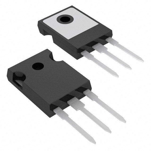
The IRFP15N60LPBF is an N-Channel MOSFET manufactured by Vishay Siliconix, rated for 600V drain-to-source voltage with 15A continuous drain current at 25°C. The device is housed in a TO-247AC through-hole package and is designed for high-voltage switching applications. The IRFP15N60LPBF is classified as obsolete, making identification of functionally equivalent substitute components necessary for ongoing design support and procurement.
Substiute Parts
Key Parameters
| Parameter | Value | Unit |
|---|---|---|
| Drain-to-Source Voltage (Vdss) | 600 | V |
| Continuous Drain Current (Id) @ 25°C | 15 | A |
| On-State Resistance (Rds On Max) @ 9A, 10V | 460 | mOhm |
| Gate Threshold Voltage (Vgs(th) Max) @ 250µA | 5 | V |
| Power Dissipation (Max) | 280 | W |
| Operating Temperature Range | -55 to 150 | °C |
| Package Type | TO-247-3 | — |
| Mounting Type | Through Hole | — |
Substitute Part Grouping Explanation
Substitution of the IRFP15N60LPBF is determined by electrical and mechanical compatibility across the following critical parameters:
Electrical Compatibility Criteria:
- Drain-to-Source Voltage (Vdss) must equal or exceed 600V
- Continuous Drain Current (Id) must meet or exceed 15A at 25°C
- On-State Resistance (Rds On) must not significantly exceed the original specification to maintain thermal performance
- Gate Threshold Voltage (Vgs(th)) must be compatible with existing gate drive circuitry
- Power Dissipation capability must support the thermal requirements of the application
- Gate Charge (Qg) and Input Capacitance (Ciss) must be within acceptable ranges to prevent gate drive circuit redesign
Mechanical Compatibility Criteria:
- Package type must be TO-247-3 or equivalent TO-247 variant
- Through-hole mounting configuration must be maintained
- Pin configuration must be compatible with existing PCB layouts
Regulatory Compliance:
- RoHS3 compliance required
- REACH unaffected status required
- Moisture Sensitivity Level (MSL) of 1 (Unlimited) required
Parameter Comparison
| Parameter | IRFP15N60LPBF (Main) | IXFH14N60P (Substitute) | STW13NK60Z (Substitute) | Unit |
|---|---|---|---|---|
| Manufacturer | Vishay Siliconix | IXYS | STMicroelectronics | — |
| Product Status | Obsolete | Active | Active | — |
| Drain-to-Source Voltage (Vdss) | 600 | 600 | 600 | V |
| Continuous Drain Current (Id) @ 25°C | 15 | 14 | 13 | A |
| On-State Resistance (Rds On Max) | 460 @ 9A, 10V | 550 @ 7A, 10V | 550 @ 4.5A, 10V | mOhm |
| Gate Threshold Voltage (Vgs(th) Max) | 5 @ 250µA | 5.5 @ 2.5mA | 4.5 @ 100µA | V |
| Gate Charge (Qg Max) @ 10V | 100 | 36 | 92 | nC |
| Input Capacitance (Ciss Max) @ 25V | 2720 | 2500 | 2030 | pF |
| Power Dissipation (Max) | 280 | 300 | 150 | W |
| Operating Temperature Range | -55 to 150 | -55 to 150 | -55 to 150 | °C |
| Package Type | TO-247AC | TO-247AD | TO-247-3 | — |
| Mounting Type | Through Hole | Through Hole | Through Hole | — |
| RoHS3 Compliance | Yes | Yes | Yes | — |
| REACH Status | Unaffected | Unaffected | Unaffected | — |
| MSL Rating | 1 (Unlimited) | 1 (Unlimited) | 1 (Unlimited) | — |
Engineering Selection Recommendations
IXFH14N60P (IXYS)
The IXFH14N60P is an active product that maintains electrical compatibility with the IRFP15N60LPBF across all critical parameters. The device meets the 600V Vdss requirement and provides 14A continuous drain current, which is within 93% of the original specification. The on-state resistance of 550 mOhm is slightly elevated compared to the original 460 mOhm, resulting in marginally higher conduction losses. The power dissipation rating of 300W exceeds the original 280W specification. Gate charge is significantly reduced at 36 nC, which may improve gate drive efficiency. The TO-247AD package is mechanically compatible with TO-247-3 layouts. This device is recommended for applications where the 1A reduction in continuous current rating is acceptable and where the lower gate charge provides system-level benefits. Full RoHS3 compliance and REACH unaffected status are confirmed.
STW13NK60Z (STMicroelectronics)
The STW13NK60Z is an active product that meets the 600V Vdss requirement with 13A continuous drain current, representing 87% of the original specification. The on-state resistance of 550 mOhm is comparable to the IXFH14N60P. The power dissipation rating of 150W is significantly lower than the original 280W specification, indicating reduced thermal capability. Gate charge of 92 nC is comparable to the original 100 nC specification. The TO-247-3 package provides direct mechanical compatibility. This device is recommended for applications where the 2A reduction in continuous current rating and 150W power dissipation limit are acceptable. Full RoHS3 compliance and REACH unaffected status are confirmed.
Both substitute parts are active products with confirmed regulatory compliance, providing long-term availability advantages over the obsolete IRFP15N60LPBF.
Frequently Asked Questions (FAQ)
Q: Can the IXFH14N60P directly replace the IRFP15N60LPBF without PCB modifications?
A: The IXFH14N60P uses a TO-247AD package, which is mechanically compatible with TO-247-3 layouts. Pin configuration is identical. However, the reduced gate charge (36 nC versus 100 nC) may require gate drive circuit evaluation to ensure adequate switching performance. PCB layout modifications are not required.
Q: What is the impact of the reduced continuous drain current in the substitute parts?
A: The IXFH14N60P provides 14A (93% of original) and the STW13NK60Z provides 13A (87% of original). Selection depends on the actual current requirements of the application. If the circuit operates below these current levels, substitution is valid. If the circuit requires the full 15A specification, neither substitute is appropriate.
Q: How does the increased on-state resistance affect thermal performance?
A: The IXFH14N60P and STW13NK60Z both specify 550 mOhm on-state resistance compared to the original 460 mOhm. This represents approximately 20% higher conduction losses. Thermal analysis of the specific application is required to determine if the increased power dissipation can be accommodated by existing heat management provisions.
Q: Are the substitute parts suitable for high-frequency switching applications?
A: The IXFH14N60P exhibits significantly lower gate charge (36 nC) compared to the original (100 nC), which may improve switching speed and reduce gate drive power consumption. The STW13NK60Z maintains comparable gate charge (92 nC). Gate drive circuit compatibility should be evaluated based on the specific switching frequency and voltage requirements of the application.
Q: What is the difference between TO-247AC and TO-247AD packages?
A: Both TO-247AC and TO-247AD are TO-247-3 variants with identical pin configurations and mechanical compatibility. The designations reflect internal manufacturing differences that do not affect electrical performance or PCB layout compatibility.
Q: Are both substitute parts available in the same packaging format as the original?
A: The IXFH14N60P is supplied in tube packaging. The STW13NK60Z packaging format is not specified in the available data. Confirm packaging availability with the supplier for your specific procurement requirements.
Q: What regulatory certifications apply to these substitute parts?
A: All three devices (IRFP15N60LPBF, IXFH14N60P, and STW13NK60Z) are RoHS3 compliant and REACH unaffected. Moisture Sensitivity Level (MSL) is 1 (Unlimited) for all devices, indicating no special moisture handling requirements during storage or assembly.
Alternative Parts

SJ6012L2TP
Littelfuse Inc.
6 Alternative Parts

JMK107BBJ476MA-RE
Taiyo Yuden
10 Alternative Parts

GMK107BBJ475MA-T
Taiyo Yuden
5 Alternative Parts
SJ6020N2ARP
Littelfuse Inc.
3 Alternative Parts
SJ6025R2ATP
Littelfuse Inc.
4 Alternative Parts

2474-05L
API Delevan Inc.
1 Alternative Parts

4590R-684K
API Delevan Inc.
1 Alternative Parts

CM6560R-334
API Delevan Inc.
1 Alternative Parts

CM6460-104
API Delevan Inc.
1 Alternative Parts

5526-12
API Delevan Inc.
1 Alternative Parts