


Request Quote
(Ships tomorrow)
IRFIBF30G N-Channel 900V 1.9A MOSFET Equivalent & Substitute Parts
Part Overview
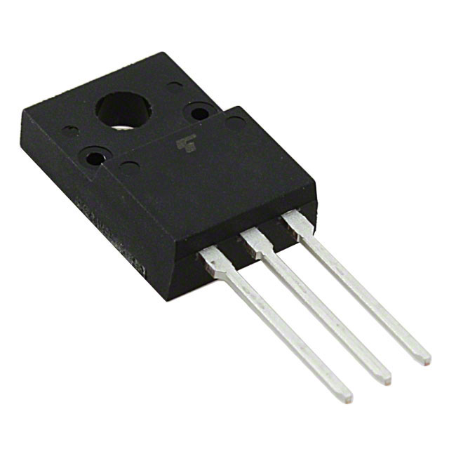
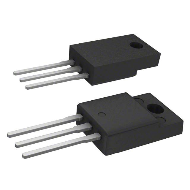
The IRFIBF30G is an N-Channel MOSFET manufactured by Vishay Siliconix, rated for 900V drain-to-source voltage with 1.9A continuous drain current at 25°C. The device is housed in a TO-220-3 through-hole package and dissipates a maximum of 35W. This part is classified as obsolete, making equivalent and substitute parts necessary for ongoing design support and procurement.
The IRFIBF30G serves in high-voltage switching applications where N-Channel MOSFET functionality is required within the 900V voltage class. Due to its obsolete status, alternative parts with equivalent or superior electrical characteristics are required to maintain design continuity and ensure component availability.
Substiute Parts
Key Parameters
| Parameter | Value | Unit |
|---|---|---|
| FET Type | N-Channel | — |
| Drain to Source Voltage (Vdss) | 900 | V |
| Continuous Drain Current (Id) @ 25°C | 1.9 | A |
| Drive Voltage (Max Rds On) | 10 | V |
| Rds On (Max) @ Id, Vgs | 3.7 @ 1.1A, 10V | Ohm |
| Gate Threshold Voltage (Vgs(th)) @ Id | 4 @ 250µA | V |
| Gate Charge (Qg) @ Vgs | 78 @ 10V | nC |
| Maximum Gate Voltage (Vgs) | ±20 | V |
| Input Capacitance (Ciss) @ Vds | 1200 @ 25V | pF |
| Power Dissipation (Max) | 35 | W |
| Operating Temperature Range | -55 to 150 | °C |
| Mounting Type | Through Hole | — |
| Package | TO-220-3 | — |
| RoHS Status | Non-compliant | — |
Substitute Part Grouping Explanation
Substitution of the IRFIBF30G is determined by the following critical electrical and mechanical parameters:
Primary Substitution Criteria:
- Drain-to-Source Voltage (Vdss): Must equal or exceed 900V
- Continuous Drain Current (Id): Must equal or exceed 1.9A at 25°C
- Gate Drive Voltage: Must support 10V operation
- Mounting Type: Must be through-hole compatible
- Package Form Factor: Must be TO-220-3 or compatible TO-220 variant
Secondary Compatibility Factors:
- Operating temperature range must encompass -55°C to 150°C
- Rds On characteristics must be suitable for the application's switching requirements
- Gate charge and input capacitance affect switching speed and driver requirements
Substitute parts are grouped into two categories:
Category 1: Direct Parametric Equivalents — Parts with identical or near-identical electrical specifications and the same base product lineage (IRFIBF30GPBF).
Category 2: Functional Substitutes — Parts from alternative manufacturers (Toshiba, onsemi, IXYS, STMicroelectronics) that meet or exceed the minimum electrical requirements while maintaining TO-220-3 package compatibility and through-hole mounting.
Parameter Comparison
| Part Number | Manufacturer | Vdss (V) | Id @ 25°C (A) | Rds On @ 10V (Ohm) | Qg @ 10V (nC) | Ciss @ 25V (pF) | Power Diss. (W) | Package | Status |
|---|---|---|---|---|---|---|---|---|---|
| IRFIBF30G | Vishay Siliconix | 900 | 1.9 | 3.7 | 78 | 1200 | 35 | TO-220-3 | Obsolete |
| IRFIBF30GPBF | Vishay Siliconix | 900 | 1.9 | 3.7 | 78 | 1200 | 35 | TO-220-3 | Active |
| 2SK3564(STA4,Q,M) | Toshiba | 900 | 3.0 | 4.3 | 17 | 700 | 40 | TO-220SIS | Active |
| 2SK3798(STA4,Q,M) | Toshiba | 900 | 4.0 | 3.5 | 26 | 800 | 40 | TO-220SIS | Active |
| BFL4026-1E | onsemi | 900 | 3.5 | 3.6 | 33 | 650 | 35 | TO-220F-3FS | Obsolete |
| FQPF4N90C | onsemi | 900 | 4.0 | 4.2 | 22 | 960 | 47 | TO-220F-3 | Active |
| IXFP4N100Q | IXYS | 1000 | 4.0 | 3.0 | 39 | 1050 | 150 | TO-220-3 | Not For New Designs |
| STF5N95K3 | STMicroelectronics | 950 | 4.0 | 3.5 | 19 | 460 | 25 | TO-220FP | Active |
| STF5NK100Z | STMicroelectronics | 1000 | 3.5 | 3.7 | 59 | 1154 | 30 | TO-220FP | Active |
| STP3NK90ZFP | STMicroelectronics | 900 | 3.0 | 4.8 | 22.7 | 590 | 25 | TO-220FP | Active |
| STP6NK90ZFP | STMicroelectronics | 900 | 5.8 | 2.0 | 60.5 | 1350 | 30 | TO-220FP | Active |
Engineering Selection Recommendations
Recommended Primary Substitute: IRFIBF30GPBF
The IRFIBF30GPBF is the direct equivalent of the IRFIBF30G, manufactured by Vishay Siliconix with identical electrical specifications. This part maintains 900V Vdss, 1.9A continuous drain current, and 35W power dissipation. The IRFIBF30GPBF is currently in active production status and is RoHS3 compliant, addressing regulatory requirements that the original IRFIBF30G does not meet. Packaging is supplied in tube format. This is the preferred substitute for direct replacement in existing designs.
Recommended Secondary Substitutes (Active Status, RoHS3 Compliant):
STMicroelectronics SuperMESH™ Series:
- STP6NK90ZFP: Exceeds IRFIBF30G specifications with 5.8A continuous drain current and 2.0Ohm Rds On at 10V. Suitable for applications requiring higher current capacity or lower on-resistance. Active product status.
- STF5N95K3: Rated for 950V Vdss with 4.0A continuous drain current and 3.5Ohm Rds On. Provides enhanced performance margin above the 900V requirement. Active product status.
- STP3NK90ZFP: Matches 900V Vdss with 3.0A continuous drain current. Suitable for applications where current requirements are moderate. Active product status.
- STF5NK100Z: Rated for 1000V Vdss with 3.5A continuous drain current. Provides maximum voltage margin for high-voltage applications. Active product status.
Toshiba π-MOSIV Series:
- 2SK3564(STA4,Q,M): Rated for 900V Vdss with 3.0A continuous drain current. Active product status with RoHS3 compliance.
- 2SK3798(STA4,Q,M): Rated for 900V Vdss with 4.0A continuous drain current and 3.5Ohm Rds On. Active product status with RoHS3 compliance.
onsemi QFET® Series:
- FQPF4N90C: Rated for 900V Vdss with 4.0A continuous drain current and 47W power dissipation. Active product status with RoHS3 compliance.
Not Recommended for New Designs:
- IXFP4N100Q: Marked as "Not For New Designs" by manufacturer. While electrically capable, this status indicates limited future support and availability.
- BFL4026-1E: Obsolete status limits long-term availability and support.
All recommended active substitutes maintain through-hole mounting and TO-220 package compatibility. Selection among active alternatives depends on specific application requirements for current capacity, on-resistance, and thermal performance.
Frequently Asked Questions (FAQ)
Q: Can IRFIBF30GPBF be used as a direct replacement for IRFIBF30G?
A: Yes. IRFIBF30GPBF is the direct parametric equivalent with identical electrical specifications: 900V Vdss, 1.9A continuous drain current, 3.7Ohm Rds On at 10V, and 35W power dissipation. The primary difference is product status (active vs. obsolete) and RoHS3 compliance. Pinout and TO-220-3 package are identical.
Q: What is the minimum drain current requirement for a substitute part?
A: The substitute must support at least 1.9A continuous drain current at 25°C to meet the IRFIBF30G specification. All listed substitutes meet or exceed this requirement.
Q: Are TO-220SIS and TO-220FP packages compatible with TO-220-3?
A: TO-220SIS and TO-220FP are variants of the TO-220 package family with identical pin configurations and through-hole mounting. They are mechanically and electrically compatible with TO-220-3 applications. Verify specific PCB footprint requirements for your design.
Q: What is the significance of the 900V Vdss rating?
A: The 900V Vdss rating specifies the maximum drain-to-source voltage the MOSFET can withstand in the off-state. Substitute parts must equal or exceed 900V to ensure safe operation in the same circuit. Parts rated at 950V or 1000V provide additional voltage margin and are acceptable substitutes.
Q: How does Rds On affect substitute selection?
A: Rds On (on-resistance) determines conduction losses and heat dissipation during switching. Lower Rds On values reduce power loss. The IRFIBF30G specifies 3.7Ohm at 1.1A and 10V. Substitutes with equal or lower Rds On values improve efficiency. Higher Rds On values increase thermal load and may require design verification.
Q: Why is RoHS3 compliance important?
A: RoHS3 compliance indicates the part meets current environmental and regulatory standards for hazardous substance restrictions. The original IRFIBF30G is RoHS non-compliant. Active substitutes with RoHS3 compliance ensure compatibility with modern procurement and environmental regulations.
Q: Can I use a substitute with higher continuous drain current?
A: Yes. Substitutes with higher continuous drain current (e.g., 3.0A, 4.0A, or 5.8A) are acceptable and provide design margin. Higher current ratings do not negatively affect applications designed for lower currents. Verify that gate drive circuitry and thermal management remain adequate.
Q: What is gate charge (Qg) and why does it vary among substitutes?
A: Gate charge is the total charge required to switch the MOSFET from off to on state. Lower gate charge reduces switching losses and allows faster switching speeds. The IRFIBF30G specifies 78nC at 10V. Substitutes with lower Qg (e.g., 17nC to 60.5nC) may improve switching performance but require verification that gate driver circuits are compatible.
Q: Are all listed substitutes available in the same packaging format?
A: No. While all substitutes use TO-220 package variants (TO-220-3, TO-220SIS, TO-220FP, TO-220F-3FS), the specific packaging format and tape/tube options vary. Verify packaging availability with your supplier for procurement requirements.
Q: What is the operating temperature range requirement?
A: The IRFIBF30G operates from -55°C to 150°C junction temperature. All listed substitutes support this full temperature range, ensuring thermal compatibility across industrial and extended temperature applications.
Q: Should I select a substitute based on lowest Rds On?
A: Not necessarily. While lower Rds On reduces conduction losses, other factors including gate charge, input capacitance, power dissipation rating, and thermal characteristics must align with your circuit design. Select the substitute that best matches your application's switching frequency, current profile, and thermal budget.
Alternative Parts

SJ6012L2TP
Littelfuse Inc.
6 Alternative Parts

JMK107BBJ476MA-RE
Taiyo Yuden
10 Alternative Parts

GMK107BBJ475MA-T
Taiyo Yuden
5 Alternative Parts
SJ6020N2ARP
Littelfuse Inc.
3 Alternative Parts
SJ6025R2ATP
Littelfuse Inc.
4 Alternative Parts

2474-05L
API Delevan Inc.
1 Alternative Parts

4590R-684K
API Delevan Inc.
1 Alternative Parts

CM6560R-334
API Delevan Inc.
1 Alternative Parts

CM6460-104
API Delevan Inc.
1 Alternative Parts

5526-12
API Delevan Inc.
1 Alternative Parts