


Request Quote
(Ships tomorrow)
IRFIBE20GPBF Equivalent & Substitute Parts
Part Overview
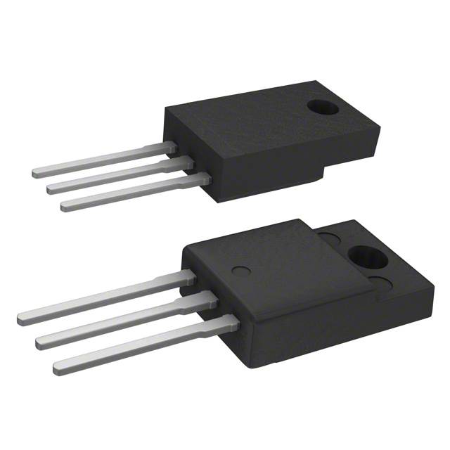
The IRFIBE20GPBF is an N-Channel MOSFET manufactured by Vishay Siliconix, rated for 800V drain-to-source voltage with 1.4A continuous drain current at 25°C. This device is packaged in a Through Hole TO-220-3 configuration and is designed for high-voltage switching applications. The part is currently Active in product status with RoHS3 compliance and unlimited moisture sensitivity level (MSL 1).
Substitute parts are identified when equivalent electrical performance can be achieved within the specified parameter ranges while maintaining compatibility with the application's thermal, voltage, and current requirements.
Substiute Parts
Key Parameters
| Parameter | Value | Unit |
|---|---|---|
| Drain to Source Voltage (Vdss) | 800 | V |
| Continuous Drain Current (Id) @ 25°C | 1.4 | A |
| Drive Voltage (Max Rds On) | 10 | V |
| Rds On (Max) @ Id, Vgs | 6.5 @ 840mA, 10V | Ohm |
| Gate Threshold Voltage Vgs(th) (Max) @ Id | 4 | V @ 250µA |
| Gate Charge (Qg) (Max) @ Vgs | 38 | nC @ 10V |
| Power Dissipation (Max) | 30 | W |
| Operating Temperature Range | -55 to 150 | °C |
| Mounting Type | Through Hole | - |
| Package / Case | TO-220-3 | - |
Substitute Part Grouping Explanation
Substitute parts for the IRFIBE20GPBF are qualified based on the following criteria:
Electrical Compatibility Requirements:
- Drain to Source Voltage (Vdss) must equal or exceed 800V
- Continuous Drain Current (Id) must meet or exceed 1.4A at 25°C
- Drive Voltage (Max Rds On) must be 10V
- Gate Threshold Voltage must be compatible with 4V specification
- Operating Temperature Range must encompass -55°C to 150°C
Mechanical Compatibility Requirements:
- Mounting Type: Through Hole
- Package Family: TO-220 variants (TO-220-3, TO-220F-3, TO-220FP)
Compliance Requirements:
- Product Status: Active
- RoHS Compliance: ROHS3 or equivalent
The identified substitute parts meet these criteria while offering variations in continuous drain current capacity, on-resistance characteristics, and gate charge specifications. These variations allow for application-specific optimization without compromising core voltage and temperature ratings.
Parameter Comparison
| Parameter | IRFIBE20GPBF (Vishay) | FQPF2N80YDTU (Fairchild) | STF3NK80Z (STMicroelectronics) |
|---|---|---|---|
| Manufacturer | Vishay Siliconix | Fairchild Semiconductor | STMicroelectronics |
| FET Type | N-Channel | N-Channel | N-Channel |
| Drain to Source Voltage (Vdss) | 800V | 800V | 800V |
| Continuous Drain Current (Id) @ 25°C | 1.4A | 1.5A | 2.5A |
| Drive Voltage (Max Rds On) | 10V | 10V | 10V |
| Rds On (Max) @ Id, Vgs | 6.5Ω @ 840mA, 10V | 6.3Ω @ 750mA, 10V | 4.5Ω @ 1.25A, 10V |
| Gate Threshold Voltage Vgs(th) (Max) @ Id | 4V @ 250µA | 5V @ 250µA | 4.5V @ 50µA |
| Gate Charge (Qg) (Max) @ Vgs | 38nC @ 10V | 15nC @ 10V | 19nC @ 10V |
| Vgs (Max) | ±20V | ±30V | ±30V |
| Input Capacitance (Ciss) (Max) @ Vds | 530pF @ 25V | 550pF @ 25V | 485pF @ 25V |
| Power Dissipation (Max) | 30W | 35W | 25W |
| Operating Temperature Range | -55°C to 150°C | -55°C to 150°C | -55°C to 150°C |
| Mounting Type | Through Hole | Through Hole | Through Hole |
| Package / Case | TO-220-3 | TO-220F-3 (Y-Forming) | TO-220FP |
| Product Status | Active | Active | Active |
| RoHS Status | ROHS3 Compliant | Not specified | ROHS3 Compliant |
Engineering Selection Recommendations
FQPF2N80YDTU (Fairchild Semiconductor): This substitute provides equivalent voltage rating (800V) with marginally higher continuous drain current (1.5A versus 1.4A). The on-resistance is slightly lower (6.3Ω versus 6.5Ω), and gate charge is significantly reduced (15nC versus 38nC), resulting in faster switching characteristics. The TO-220F-3 package features formed leads (Y-Forming) rather than straight leads, which may require PCB layout adjustment. Power dissipation rating is higher at 35W. Product status is Active. This part is suitable for applications requiring improved switching speed and thermal headroom.
STF3NK80Z (STMicroelectronics): This substitute offers the highest continuous drain current rating (2.5A) and the lowest on-resistance (4.5Ω), providing superior current handling and reduced conduction losses. Gate charge is moderate (19nC), and input capacitance is the lowest among the three options (485pF). The TO-220FP package is a standard through-hole variant. Product status is Active with ROHS3 compliance and REACH Unaffected designation. This part is suitable for applications requiring maximum current capacity and efficiency optimization. Power dissipation rating is 25W, which is lower than the original part despite higher current capability due to improved on-resistance characteristics.
All three parts maintain the 800V voltage rating, -55°C to 150°C operating temperature range, and Through Hole mounting compatibility required for direct substitution.
Frequently Asked Questions (FAQ)
Q: Can the FQPF2N80YDTU replace the IRFIBE20GPBF in all applications?
A: The FQPF2N80YDTU meets the core electrical requirements (800V, 1.5A minimum current, 10V drive voltage) and operating temperature range. The primary consideration is the TO-220F-3 package with formed leads, which differs from the TO-220-3 straight-lead package of the original part. PCB footprint and lead spacing must be verified for compatibility. The reduced gate charge (15nC versus 38nC) results in faster switching, which may require gate drive circuit evaluation in sensitive applications.
Q: What are the advantages of the STF3NK80Z substitute?
A: The STF3NK80Z provides superior on-resistance (4.5Ω versus 6.5Ω), enabling lower conduction losses and reduced heat generation. The higher continuous drain current rating (2.5A) provides additional design margin. Gate charge is moderate (19nC), and input capacitance is the lowest among the three options. These characteristics make it suitable for high-efficiency applications and designs requiring thermal optimization.
Q: Are there package compatibility issues between the three parts?
A: All three parts use Through Hole mounting in TO-220 family packages. The IRFIBE20GPBF uses TO-220-3 with straight leads, the FQPF2N80YDTU uses TO-220F-3 with formed leads (Y-Forming), and the STF3NK80Z uses TO-220FP. While all are mechanically compatible with standard TO-220 footprints, the formed leads of the FQPF2N80YDTU may require PCB layout verification. The STF3NK80Z uses a standard TO-220FP package with straight leads, providing direct mechanical compatibility with the original part.
Q: Which substitute should be selected for a cost-optimized design?
A: Part selection based on cost requires inventory and pricing data not provided in this technical reference. Consult with component suppliers for current pricing and availability. The STF3NK80Z has significantly higher inventory (45,300 pieces) compared to the FQPF2N80YDTU (2,900 pieces), which may influence lead time and cost considerations.
Q: Are all three parts RoHS compliant?
A: The IRFIBE20GPBF and STF3NK80Z are explicitly ROHS3 compliant. The FQPF2N80YDTU RoHS status is not specified in the provided data. Verify RoHS compliance with the supplier if this is a requirement for your application.
Q: What is the impact of different gate charge specifications on circuit design?
A: Gate charge (Qg) affects the gate drive circuit requirements and switching speed. The IRFIBE20GPBF has 38nC, the FQPF2N80YDTU has 15nC, and the STF3NK80Z has 19nC. Lower gate charge enables faster switching transitions and reduces gate drive power consumption. If the original design uses a fixed gate drive circuit, the reduced gate charge of the FQPF2N80YDTU may result in faster switching, which could introduce EMI or timing issues in sensitive applications. The STF3NK80Z provides a moderate gate charge value suitable for most applications.
Alternative Parts

SJ6012L2TP
Littelfuse Inc.
6 Alternative Parts

JMK107BBJ476MA-RE
Taiyo Yuden
10 Alternative Parts

GMK107BBJ475MA-T
Taiyo Yuden
5 Alternative Parts
SJ6020N2ARP
Littelfuse Inc.
3 Alternative Parts
SJ6025R2ATP
Littelfuse Inc.
4 Alternative Parts

2474-05L
API Delevan Inc.
1 Alternative Parts

4590R-684K
API Delevan Inc.
1 Alternative Parts

CM6560R-334
API Delevan Inc.
1 Alternative Parts

CM6460-104
API Delevan Inc.
1 Alternative Parts

5526-12
API Delevan Inc.
1 Alternative Parts