


Request Quote
(Ships tomorrow)
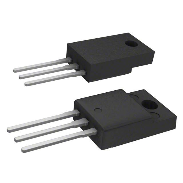
IRFIBE20G N-Channel 800V 1.4A MOSFET Equivalent & Substitute Parts
Part Overview
The IRFIBE20G is an N-Channel MOSFET manufactured by Vishay Siliconix, rated for 800V drain-to-source voltage with 1.4A continuous drain current at 25°C. This device is packaged in a TO-220-3 configuration with an isolated tab and is designed for through-hole mounting applications. The part is currently classified as obsolete, making identification of equivalent and substitute components necessary for ongoing system support, design updates, and procurement continuity. Substitute parts must maintain electrical compatibility across critical parameters including voltage rating, current capacity, on-resistance characteristics, and thermal performance while accommodating available packaging and compliance options.
Substiute Parts
Key Parameters
| Parameter | Value | Unit |
|---|---|---|
| FET Type | N-Channel | — |
| Drain to Source Voltage (Vdss) | 800 | V |
| Current - Continuous Drain (Id) @ 25°C | 1.4 | A (Tc) |
| Rds On (Max) @ Id, Vgs | 6.5 | Ohm @ 840mA, 10V |
| Power Dissipation (Max) | 30 | W (Tc) |
| Operating Temperature Range | -55 to 150 | °C (TJ) |
| Mounting Type | Through Hole | — |
| Package / Case | TO-220-3 Full Pack, Isolated Tab | — |
| Product Status | Obsolete | — |
Substitute Part Grouping Explanation
Substitution of the IRFIBE20G is determined by strict adherence to the following electrical and mechanical criteria:
Primary Substitution Criteria:
- Drain-to-Source Voltage (Vdss): Must equal or exceed 800V
- Continuous Drain Current (Id): Must equal or exceed 1.4A at 25°C
- On-Resistance (Rds On): Must not exceed 6.5 Ohm at specified gate voltage
- Power Dissipation: Must equal or exceed 30W (Tc)
- Operating Temperature Range: Must encompass -55°C to 150°C (TJ)
- Mounting Type: Through Hole configuration required
- Package Compatibility: TO-220-3 or mechanically compatible variants
Secondary Considerations:
- Gate Charge (Qg) and Input Capacitance (Ciss) for circuit performance
- Gate Threshold Voltage (Vgs(th)) for drive circuit compatibility
- Product Status and RoHS compliance for procurement and regulatory requirements
Substitute parts are grouped into two categories: parametric equivalents (matching all critical electrical specifications) and manufacturer-recommended alternatives (meeting or exceeding performance requirements with potential enhancements).
Parameter Comparison
| Parameter | IRFIBE20G | IRFIBE20GPBF | FQPF2N80YDTU | IXFP4N100Q | STF3NK80Z |
|---|---|---|---|---|---|
| Manufacturer | Vishay Siliconix | Vishay Siliconix | Fairchild Semiconductor | IXYS | STMicroelectronics |
| FET Type | N-Channel | N-Channel | N-Channel | N-Channel | N-Channel |
| Vdss (V) | 800 | 800 | 800 | 1000 | 800 |
| Id @ 25°C (A) | 1.4 | 1.4 | 1.5 | 4 | 2.5 |
| Rds On (Max) @ 10V (Ohm) | 6.5 | 6.5 | 6.3 | 3 | 4.5 |
| Power Dissipation (Max) (W) | 30 | 30 | 35 | 150 | 25 |
| Operating Temperature (°C) | -55 to 150 | -55 to 150 | -55 to 150 | -55 to 150 | -55 to 150 |
| Mounting Type | Through Hole | Through Hole | Through Hole | Through Hole | Through Hole |
| Package / Case | TO-220-3 Full Pack, Isolated Tab | TO-220-3 Full Pack, Isolated Tab | TO-220F-3 (Y-Forming) | TO-220-3 | TO-220FP |
| Product Status | Obsolete | Active | Active | Not For New Designs | Active |
| RoHS Status | Non-compliant | ROHS3 Compliant | Not specified | ROHS3 Compliant | ROHS3 Compliant |
| Vgs(th) (Max) @ Id (V) | 4 @ 250µA | 4 @ 250µA | 5 @ 250µA | 5 @ 1.5mA | 4.5 @ 50µA |
| Gate Charge (Qg) (Max) @ 10V (nC) | 38 | 38 | 15 | 39 | 19 |
| Input Capacitance (Ciss) (Max) @ 25V (pF) | 530 | 530 | 550 | 1050 | 485 |
| Vgs (Max) (±V) | 20 | 20 | 30 | 20 | 30 |
Engineering Selection Recommendations
IRFIBE20GPBF (Vishay Siliconix) — Parametric Equivalent
The IRFIBE20GPBF is an exact parametric equivalent to the IRFIBE20G, offering identical electrical specifications across all critical parameters: 800V Vdss, 1.4A continuous drain current, 6.5 Ohm Rds On, and 30W power dissipation. The primary distinction is product status: IRFIBE20GPBF is active and ROHS3 compliant, whereas the original IRFIBE20G is obsolete and non-compliant. Packaging differs only in supplier configuration (tube versus bulk), with both utilizing the TO-220-3 Full Pack isolated tab format. This part is the direct replacement for legacy system support and new procurement.
STF3NK80Z (STMicroelectronics) — Performance-Enhanced Substitute
The STF3NK80Z maintains the 800V voltage rating and exceeds the current requirement with 2.5A continuous drain current. On-resistance is improved at 4.5 Ohm (versus 6.5 Ohm), resulting in lower power dissipation and improved thermal performance. Gate charge is significantly reduced to 19 nC, enabling faster switching characteristics. The device is ROHS3 compliant and active in production. Package variant is TO-220FP with formed leads, mechanically compatible with standard TO-220-3 footprints. This substitute is suitable for applications requiring enhanced current capacity and reduced switching losses.
FQPF2N80YDTU (Fairchild Semiconductor) — Functional Equivalent with Enhanced Ratings
The FQPF2N80YDTU maintains 800V Vdss and provides 1.5A continuous drain current, marginally exceeding the original specification. Power dissipation is rated at 35W, providing additional thermal margin. On-resistance is 6.3 Ohm, slightly lower than the original. Gate charge is substantially reduced to 15 nC, supporting improved switching performance. The package is TO-220F-3 with Y-forming leads, mechanically compatible with standard TO-220-3 mounting. This part is active in production and suitable for direct substitution with minor performance improvements.
IXFP4N100Q (IXYS) — Higher-Voltage Alternative
The IXFP4N100Q is rated for 1000V Vdss, exceeding the original 800V specification, and provides 4A continuous drain current with 3 Ohm on-resistance. Power dissipation capability is 150W, substantially higher than the original 30W. This device is designated "Not For New Designs" and should be used only for legacy system maintenance where higher voltage margin is beneficial. The TO-220-3 package is mechanically compatible. This substitute is appropriate only when elevated voltage rating and current capacity are required and product status constraints are acceptable.
Frequently Asked Questions (FAQ)
Q: Can IRFIBE20GPBF be used as a direct replacement for IRFIBE20G?
A: Yes. IRFIBE20GPBF is a parametric equivalent with identical electrical specifications. The primary difference is product status (active versus obsolete) and RoHS compliance (ROHS3 compliant versus non-compliant). Both devices share the same TO-220-3 Full Pack isolated tab package and are electrically interchangeable.
Q: What is the primary advantage of STF3NK80Z over the original IRFIBE20G?
A: STF3NK80Z provides improved performance through reduced on-resistance (4.5 Ohm versus 6.5 Ohm) and significantly lower gate charge (19 nC versus 38 nC). These characteristics result in lower power dissipation, reduced switching losses, and faster switching response. Current capacity is also increased to 2.5A. The device maintains the 800V voltage rating and is ROHS3 compliant.
Q: Are the TO-220F-3 and TO-220FP packages compatible with TO-220-3 footprints?
A: TO-220F-3 (Y-forming) and TO-220FP packages are mechanically compatible with standard TO-220-3 through-hole mounting. The primary difference is lead forming: Y-forming and FP variants have pre-formed leads for automated insertion, while standard TO-220-3 has straight leads. Both configurations mount to identical PCB hole patterns and use the same mounting hardware.
Q: Why is IXFP4N100Q marked "Not For New Designs"?
A: IXFP4N100Q is designated "Not For New Designs" by the manufacturer, indicating the product line is in end-of-life status. While the device remains available and functional, IXYS recommends alternative parts for new circuit designs. This part is suitable only for legacy system maintenance and repair where existing designs require this specific device.
Q: What is the impact of gate charge differences between substitute parts?
A: Gate charge (Qg) directly affects switching speed and drive circuit requirements. Lower gate charge (STF3NK80Z at 19 nC, FQPF2N80YDTU at 15 nC) enables faster switching transitions and reduces drive circuit power consumption compared to the original IRFIBE20G (38 nC). Higher gate charge (IXFP4N100Q at 39 nC) requires more drive current but is comparable to the original specification.
Q: Can substitute parts with higher current ratings be used in applications designed for 1.4A?
A: Yes. Substitute parts with higher current ratings (STF3NK80Z at 2.5A, FQPF2N80YDTU at 1.5A, IXFP4N100Q at 4A) are suitable for applications designed for lower current. The device will operate within its safe operating area at reduced current levels. Verify that on-resistance and power dissipation characteristics remain acceptable for the specific application.
Q: What compliance considerations apply to substitute part selection?
A: IRFIBE20G is RoHS non-compliant. For new designs and systems requiring RoHS compliance, select IRFIBE20GPBF, STF3NK80Z, or IXFP4N100Q, all of which are ROHS3 compliant. FQPF2N80YDTU compliance status is not specified in available documentation. All substitute parts are REACH unaffected and classified as EAR99 for export control purposes.
Q: How do input capacitance differences affect circuit performance?
A: Input capacitance (Ciss) affects gate drive circuit impedance and switching transient response. The original IRFIBE20G and IRFIBE20GPBF both specify 530 pF. STF3NK80Z (485 pF) and FQPF2N80YDTU (550 pF) are comparable. IXFP4N100Q (1050 pF) has significantly higher capacitance, requiring higher drive current and potentially affecting switching speed in high-frequency applications.
Alternative Parts

SJ6012L2TP
Littelfuse Inc.
6 Alternative Parts

JMK107BBJ476MA-RE
Taiyo Yuden
10 Alternative Parts

GMK107BBJ475MA-T
Taiyo Yuden
5 Alternative Parts
SJ6020N2ARP
Littelfuse Inc.
3 Alternative Parts
SJ6025R2ATP
Littelfuse Inc.
4 Alternative Parts

2474-05L
API Delevan Inc.
1 Alternative Parts

4590R-684K
API Delevan Inc.
1 Alternative Parts

CM6560R-334
API Delevan Inc.
1 Alternative Parts

CM6460-104
API Delevan Inc.
1 Alternative Parts

5526-12
API Delevan Inc.
1 Alternative Parts