


Request Quote
(Ships tomorrow)
IRFI614GPBF N-Channel MOSFET 250V 2.1A Equivalent & Substitute Parts
Part Overview
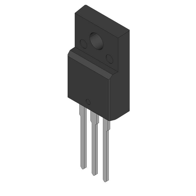
The IRFI614GPBF is an N-Channel Metal Oxide Semiconductor Field Effect Transistor (MOSFET) manufactured by Vishay Siliconix, rated for 250V drain-to-source voltage with a continuous drain current of 2.1A at 25°C. The device is packaged in a Through Hole TO-220-3 configuration and is currently in Active product status. This component is used in switching applications requiring moderate voltage and current handling in a standard through-hole form factor. Substitute parts are identified based on matching or exceeding critical electrical parameters including drain-to-source voltage rating, continuous drain current capability, gate charge characteristics, and thermal performance, while maintaining compatible packaging and mounting specifications.
Substiute Parts
Key Parameters
| Parameter | Value | Unit |
|---|---|---|
| Drain to Source Voltage (Vdss) | 250 | V |
| Current - Continuous Drain (Id) @ 25°C | 2.1 | A (Tc) |
| Drive Voltage (Max Rds On) | 10 | V |
| Rds On (Max) @ Id, Vgs | 2 | Ohm @ 1.3A, 10V |
| Vgs(th) (Max) @ Id | 4 | V @ 250µA |
| Gate Charge (Qg) (Max) @ Vgs | 8.2 | nC @ 10V |
| Power Dissipation (Max) | 23 | W (Tc) |
| Operating Temperature Range | -55 to 150 | °C (TJ) |
| Mounting Type | Through Hole | TO-220-3 |
| Vgs (Max) | ±20 | V |
| Input Capacitance (Ciss) (Max) @ Vds | 140 | pF @ 25V |
Substitute Part Grouping Explanation
Substitute parts for the IRFI614GPBF are qualified based on the following critical electrical and mechanical parameters:
Voltage Rating Compatibility: All substitute parts must maintain a Drain to Source Voltage (Vdss) rating equal to or greater than 250V to ensure safe operation in the same circuit topology.
Current Handling Capability: Substitute parts must support a continuous drain current (Id) at 25°C equal to or exceeding 2.1A to perform equivalent switching functions without thermal derating.
Gate Drive Voltage: All qualified substitutes operate at a maximum Rds On specification point of 10V gate-source voltage, ensuring compatibility with standard gate driver circuits.
On-State Resistance: Rds On characteristics must be comparable to enable equivalent power dissipation and thermal performance in the application circuit.
Gate Charge: Gate charge (Qg) values determine switching speed and driver power requirements; substitutes with lower gate charge reduce driver stress while maintaining switching performance.
Thermal Performance: Power dissipation rating and operating temperature range must support the thermal requirements of the target application.
Package and Mounting: All substitutes utilize Through Hole mounting in TO-220 package variants, maintaining mechanical compatibility with existing PCB layouts and heatsink interfaces.
Parameter Comparison
| Parameter | IRFI614GPBF (Main) | FQPF3N25 (Substitute) | IRFI4229PBF (Substitute) |
|---|---|---|---|
| Manufacturer | Vishay Siliconix | Fairchild Semiconductor | Infineon Technologies |
| FET Type | N-Channel | N-Channel | N-Channel |
| Technology | MOSFET (Metal Oxide) | MOSFET (Metal Oxide) | MOSFET (Metal Oxide) |
| Drain to Source Voltage (Vdss) | 250 V | 250 V | 250 V |
| Current - Continuous Drain (Id) @ 25°C | 2.1 A (Tc) | 2.3 A (Tc) | 19 A (Tc) |
| Drive Voltage (Max Rds On) | 10 V | 10 V | 10 V |
| Rds On (Max) @ Id, Vgs | 2 Ohm @ 1.3A, 10V | 2.2 Ohm @ 1.15A, 10V | 46 mOhm @ 11A, 10V |
| Vgs(th) (Max) @ Id | 4 V @ 250µA | 5 V @ 250µA | 5 V @ 250µA |
| Gate Charge (Qg) (Max) @ Vgs | 8.2 nC @ 10V | 5.2 nC @ 10V | 110 nC @ 10V |
| Vgs (Max) | ±20 V | ±30 V | ±30 V |
| Input Capacitance (Ciss) (Max) @ Vds | 140 pF @ 25V | 170 pF @ 25V | 4480 pF @ 25V |
| Power Dissipation (Max) | 23 W (Tc) | 27 W (Tc) | 46 W (Tc) |
| Operating Temperature Range | -55 to 150 °C (TJ) | -55 to 150 °C (TJ) | -40 to 150 °C (TJ) |
| Mounting Type | Through Hole | Through Hole | Through Hole |
| Package / Case | TO-220-3 Full Pack, Isolated Tab | TO-220-3 Full Pack | TO-220-3 |
| Product Status | Active | Active | Obsolete |
| RoHS Status | ROHS3 Compliant | Not specified | ROHS3 Compliant |
Engineering Selection Recommendations
FQPF3N25 (Fairchild Semiconductor): This substitute provides direct electrical compatibility with the IRFI614GPBF across all critical parameters. The FQPF3N25 delivers 2.3A continuous drain current, exceeding the 2.1A requirement of the main part. Gate charge is reduced to 5.2 nC, enabling faster switching with lower driver power consumption. Power dissipation capability is increased to 27W, providing thermal margin. The device maintains the same 250V voltage rating and 10V gate drive specification. Operating temperature range matches the main part at -55°C to 150°C. This part is in Active product status and suitable for direct substitution in new designs and production applications.
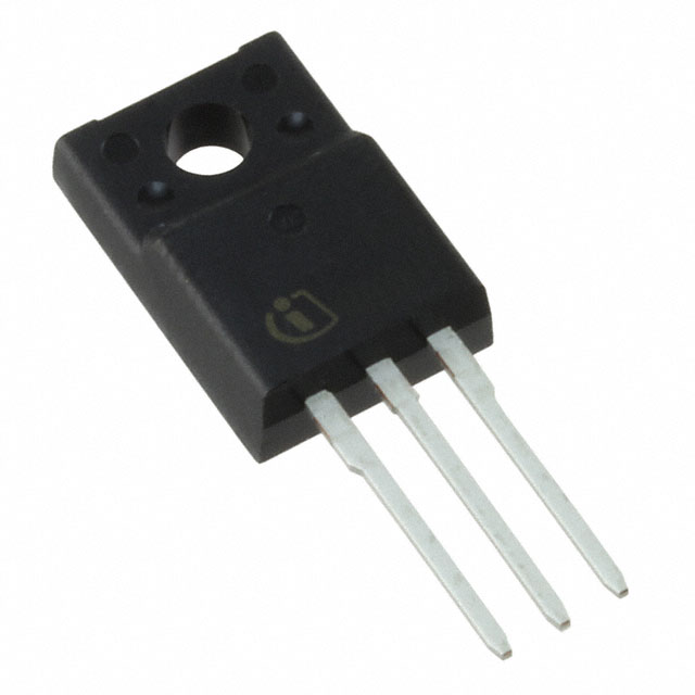
IRFI4229PBF (Infineon Technologies): This substitute is electrically qualified for the IRFI614GPBF application based on matching voltage rating (250V) and gate drive voltage (10V). However, this part is classified as Obsolete and should not be selected for new production designs or long-term supply requirements. The IRFI4229PBF provides significantly higher current capability (19A) and lower on-state resistance (46 mOhm), making it suitable only for applications requiring enhanced performance specifications. The substantially higher gate charge (110 nC) and input capacitance (4480 pF) indicate different switching characteristics that may require circuit redesign. The minimum operating temperature is -40°C, which is 15°C higher than the main part specification. This part is retained in the substitute list for legacy system support and repair applications only.
Frequently Asked Questions (FAQ)
Q: Can the FQPF3N25 be used as a direct replacement for the IRFI614GPBF without circuit modification?
A: Yes. The FQPF3N25 meets or exceeds all critical electrical parameters of the IRFI614GPBF, including voltage rating (250V), continuous drain current (2.3A vs. 2.1A), gate drive voltage (10V), and operating temperature range (-55°C to 150°C). Both devices use Through Hole TO-220-3 packaging with compatible pinouts and heatsink interfaces. No circuit modification is required.
Q: What is the primary advantage of the FQPF3N25 over the IRFI614GPBF?
A: The FQPF3N25 features reduced gate charge (5.2 nC versus 8.2 nC), resulting in faster switching transitions and lower gate driver power consumption. Additionally, the FQPF3N25 provides higher power dissipation capability (27W versus 23W), offering improved thermal margin in applications operating near maximum ratings.
Q: Why is the IRFI4229PBF listed as Obsolete, and should it be used in new designs?
A: The IRFI4229PBF is classified as Obsolete and should not be selected for new production designs due to uncertain long-term availability and supply continuity. This part is retained in the substitute list for legacy system maintenance and repair applications only. The FQPF3N25 is the recommended substitute for all new applications.
Q: Are there packaging differences between the IRFI614GPBF and the FQPF3N25?
A: Both devices use Through Hole TO-220-3 packaging. The IRFI614GPBF specifies an isolated tab configuration, while the FQPF3N25 uses a standard full pack configuration. Both packages are mechanically compatible with standard TO-220 heatsinks and PCB layouts. Pin assignments and electrical connections are identical.
Q: What is the significance of the gate charge (Qg) difference between these parts?
A: Gate charge determines the amount of charge required to switch the MOSFET on and off. Lower gate charge (FQPF3N25 at 5.2 nC) reduces switching losses and gate driver power requirements compared to higher gate charge (IRFI614GPBF at 8.2 nC). This results in improved efficiency and reduced thermal stress on the gate driver circuit.
Q: Can the IRFI4229PBF be used in place of the IRFI614GPBF for applications requiring higher current capability?
A: The IRFI4229PBF is electrically qualified for the same 250V voltage rating and 10V gate drive specification. However, the substantially higher gate charge (110 nC) and input capacitance (4480 pF) require gate driver circuits with higher current capability. The minimum operating temperature of -40°C is 15°C higher than the IRFI614GPBF specification. Use of this part in new designs is not recommended due to its Obsolete status.
Q: What compliance certifications apply to these substitute parts?
A: The IRFI614GPBF and IRFI4229PBF are both ROHS3 Compliant. The FQPF3N25 compliance status is not specified in the provided data. All three parts carry ECCN classification EAR99. The IRFI614GPBF and IRFI4229PBF are classified as REACH Unaffected or REACH Unaffected status where specified.
Q: How do the input capacitance values affect circuit performance?
A: Input capacitance (Ciss) affects the gate drive circuit's charging time and power dissipation. The IRFI614GPBF and FQPF3N25 have comparable input capacitance values (140 pF and 170 pF respectively), ensuring similar gate drive requirements. The IRFI4229PBF exhibits significantly higher input capacitance (4480 pF), requiring substantially higher gate driver current and potentially affecting switching speed in circuits with limited driver capability.
Alternative Parts

SJ6012L2TP
Littelfuse Inc.
6 Alternative Parts

JMK107BBJ476MA-RE
Taiyo Yuden
10 Alternative Parts

GMK107BBJ475MA-T
Taiyo Yuden
5 Alternative Parts
SJ6020N2ARP
Littelfuse Inc.
3 Alternative Parts
SJ6025R2ATP
Littelfuse Inc.
4 Alternative Parts

2474-05L
API Delevan Inc.
1 Alternative Parts

4590R-684K
API Delevan Inc.
1 Alternative Parts

CM6560R-334
API Delevan Inc.
1 Alternative Parts

CM6460-104
API Delevan Inc.
1 Alternative Parts

5526-12
API Delevan Inc.
1 Alternative Parts