


Request Quote
(Ships tomorrow)
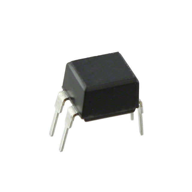
IRFD9014 P-Channel MOSFET Equivalent & Substitute Parts
Part Overview
The IRFD9014 is a P-Channel Metal Oxide Semiconductor Field Effect Transistor (MOSFET) rated for 60V drain-to-source voltage with a continuous drain current of 1.1A at 25°C. The device is packaged in a 4-HVMDIP through-hole configuration and is designed for general-purpose switching and amplification applications requiring P-channel functionality in compact form factors.
The IRFD9014 carries an obsolete product status. Identification of functionally equivalent alternatives is necessary to ensure design continuity, maintain supply chain reliability, and support ongoing production requirements for applications currently utilizing this component.
Substiute Parts
Key Parameters
| Parameter | Value | Unit |
|---|---|---|
| FET Type | P-Channel | — |
| Drain to Source Voltage (Vdss) | 60 | V |
| Continuous Drain Current (Id) @ 25°C | 1.1 | A (Ta) |
| On-State Resistance (Rds On Max) @ 660mA, 10V | 500 | mOhm |
| Gate Threshold Voltage (Vgs(th) Max) @ 250µA | 4 | V |
| Gate Charge (Qg Max) @ 10V | 12 | nC |
| Maximum Gate Voltage (Vgs Max) | ±20 | V |
| Input Capacitance (Ciss Max) @ 25V | 270 | pF |
| Power Dissipation (Max) | 1.3 | W (Ta) |
| Operating Temperature Range | -55 to 175 | °C (TJ) |
| Mounting Type | Through Hole | — |
| Package / Case | 4-DIP (0.300", 7.62mm) | — |
| Supplier Device Package | 4-HVMDIP | — |
Substitute Part Grouping Explanation
Substitution of the IRFD9014 is determined by electrical and mechanical parameter equivalence across the following critical specifications:
Electrical Parameters:
- FET channel type (P-Channel)
- Drain-to-source voltage rating (60V)
- Continuous drain current capability (1.1A @ 25°C)
- On-state resistance characteristics (500mOhm @ 660mA, 10V)
- Gate threshold voltage (4V @ 250µA)
- Gate charge (12nC @ 10V)
- Maximum gate voltage (±20V)
- Input capacitance (270pF @ 25V)
- Power dissipation rating (1.3W)
- Operating temperature range (-55°C to 175°C)
Mechanical Parameters:
- Through-hole mounting configuration
- 4-DIP package footprint (0.300", 7.62mm)
- 4-HVMDIP supplier device package designation
Substitute parts must maintain identical electrical performance across all specified operating conditions and occupy the same physical footprint to ensure direct board-level compatibility without design modification.
Parameter Comparison
| Parameter | IRFD9014 | IRFD9014PBF | Match |
|---|---|---|---|
| Manufacturer | Vishay Siliconix | Vishay Siliconix | Yes |
| FET Type | P-Channel | P-Channel | Yes |
| Drain to Source Voltage (Vdss) | 60 V | 60 V | Yes |
| Continuous Drain Current (Id) @ 25°C | 1.1 A (Ta) | 1.1 A (Ta) | Yes |
| Rds On (Max) @ 660mA, 10V | 500 mOhm | 500 mOhm | Yes |
| Vgs(th) (Max) @ 250µA | 4 V | 4 V | Yes |
| Gate Charge (Qg Max) @ 10V | 12 nC | 12 nC | Yes |
| Vgs (Max) | ±20 V | ±20 V | Yes |
| Input Capacitance (Ciss Max) @ 25V | 270 pF | 270 pF | Yes |
| Power Dissipation (Max) | 1.3 W (Ta) | 1.3 W (Ta) | Yes |
| Operating Temperature | -55°C ~ 175°C (TJ) | -55°C ~ 175°C (TJ) | Yes |
| Mounting Type | Through Hole | Through Hole | Yes |
| Package / Case | 4-DIP (0.300", 7.62mm) | 4-DIP (0.300", 7.62mm) | Yes |
| Supplier Device Package | 4-HVMDIP | 4-HVMDIP | Yes |
| Product Status | Obsolete | Active | Different |
| RoHS Status | RoHS non-compliant | ROHS3 Compliant | Different |
Engineering Selection Recommendations
The IRFD9014PBF is a direct electrical and mechanical equivalent to the IRFD9014. All specified electrical parameters, including voltage ratings, current capabilities, on-state resistance, gate characteristics, and thermal specifications, are identical. Both devices utilize the same 4-HVMDIP through-hole package footprint, enabling direct board-level substitution without PCB redesign.
The primary distinction between these parts is product lifecycle status and regulatory compliance. The IRFD9014 is classified as obsolete, whereas the IRFD9014PBF maintains active product status with current manufacturing support. The IRFD9014PBF additionally carries ROHS3 compliance certification, whereas the IRFD9014 is RoHS non-compliant. Both devices are REACH unaffected and carry identical ECCN and HTSUS classifications.
For new designs and ongoing production requiring P-channel MOSFET functionality at 60V and 1.1A ratings, the IRFD9014PBF is the appropriate selection. For legacy applications currently utilizing the IRFD9014, substitution with the IRFD9014PBF provides functional continuity with enhanced regulatory compliance and assured supply chain availability.
Frequently Asked Questions (FAQ)
Q: Can the IRFD9014PBF be used as a direct replacement for the IRFD9014 without circuit modification?
A: Yes. The IRFD9014PBF is electrically and mechanically identical to the IRFD9014 across all specified parameters. The 4-DIP through-hole package footprint is identical, and all electrical characteristics including voltage ratings, current ratings, on-state resistance, and thermal specifications match exactly. Direct substitution on existing PCBs is supported without design changes.
Q: What is the difference between the IRFD9014 and IRFD9014PBF?
A: The IRFD9014 and IRFD9014PBF are functionally equivalent P-channel MOSFETs with identical electrical specifications. The IRFD9014 is classified as obsolete with RoHS non-compliant status. The IRFD9014PBF is an active product with ROHS3 compliance certification. Both devices are manufactured by Vishay Siliconix and share the same base product number.
Q: Are there any packaging differences between these parts?
A: No. Both the IRFD9014 and IRFD9014PBF utilize the 4-HVMDIP through-hole package with a 4-DIP footprint measuring 0.300" (7.62mm). The only packaging distinction is that the IRFD9014PBF is supplied in bulk packaging, whereas the IRFD9014 packaging type is not specified in available documentation.
Q: What are the key electrical parameters that define substitution compatibility for this device?
A: Substitution compatibility is determined by matching the following parameters: P-channel FET type, 60V drain-to-source voltage rating, 1.1A continuous drain current at 25°C, 500mOhm on-state resistance at 660mA and 10V gate voltage, 4V gate threshold voltage at 250µA, 12nC gate charge at 10V, ±20V maximum gate voltage, 270pF input capacitance at 25V, 1.3W power dissipation rating, and -55°C to 175°C operating temperature range.
Q: Is the IRFD9014PBF suitable for new product designs?
A: Yes. The IRFD9014PBF is an active product with current manufacturing support and ROHS3 compliance certification. It is appropriate for new designs requiring a P-channel MOSFET with 60V rating and 1.1A continuous current capability in a through-hole 4-DIP package configuration.
Q: What compliance certifications apply to the IRFD9014PBF?
A: The IRFD9014PBF carries ROHS3 compliance certification, indicating conformance to Restriction of Hazardous Substances Directive requirements. Both the IRFD9014 and IRFD9014PBF are REACH unaffected and classified under ECCN EAR99 with HTSUS code 8541.29.0095.
Alternative Parts

SJ6012L2TP
Littelfuse Inc.
6 Alternative Parts

JMK107BBJ476MA-RE
Taiyo Yuden
10 Alternative Parts

GMK107BBJ475MA-T
Taiyo Yuden
5 Alternative Parts
SJ6020N2ARP
Littelfuse Inc.
3 Alternative Parts
SJ6025R2ATP
Littelfuse Inc.
4 Alternative Parts

2474-05L
API Delevan Inc.
1 Alternative Parts

4590R-684K
API Delevan Inc.
1 Alternative Parts

CM6560R-334
API Delevan Inc.
1 Alternative Parts

CM6460-104
API Delevan Inc.
1 Alternative Parts

5526-12
API Delevan Inc.
1 Alternative Parts