


Request Quote
(Ships tomorrow)
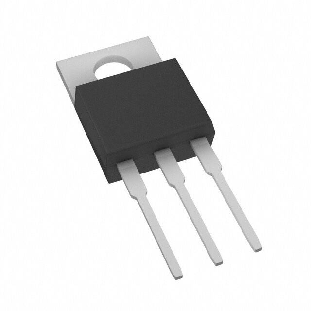
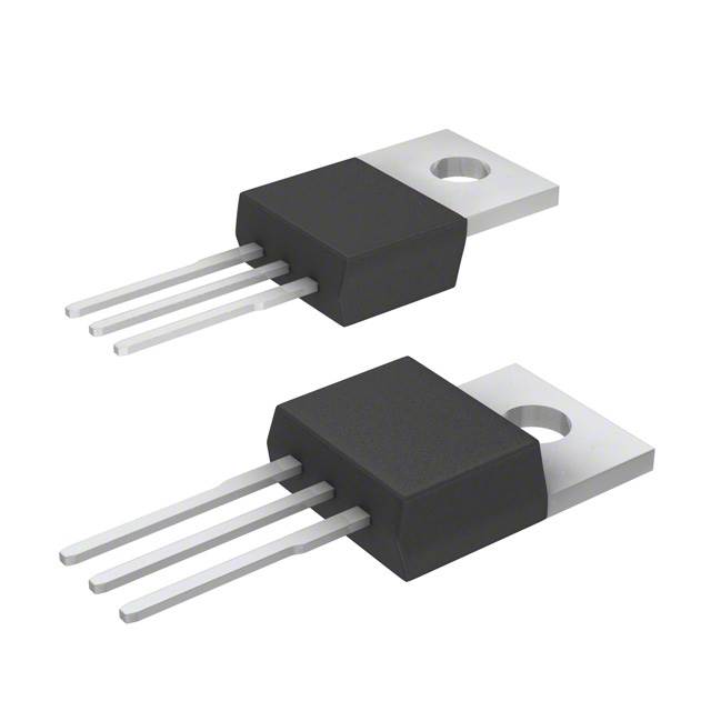
IRFBE20 N-Channel MOSFET 800V 1.8A TO-220AB Equivalent & Substitute Parts
Part Overview
The IRFBE20 is an N-Channel MOSFET manufactured by Vishay Siliconix, rated for 800V drain-to-source voltage with 1.8A continuous drain current at 25°C. The device is housed in a TO-220AB through-hole package and dissipates a maximum of 54W at the case temperature. This part is classified as obsolete, making equivalent and substitute parts necessary for ongoing design support and procurement continuity. Substitute parts must maintain electrical compatibility across voltage, current, and thermal specifications while accommodating modern component availability and compliance requirements.
Substiute Parts
Key Parameters
| Parameter | Value | Unit |
|---|---|---|
| FET Type | N-Channel | — |
| Drain to Source Voltage (Vdss) | 800 | V |
| Continuous Drain Current (Id) @ 25°C | 1.8 | A |
| Rds On (Max) @ Id, Vgs | 6.5 | Ohm @ 1.1A, 10V |
| Gate Threshold Voltage Vgs(th) (Max) @ Id | 4 | V @ 250µA |
| Gate Charge (Qg) (Max) @ Vgs | 38 | nC @ 10V |
| Power Dissipation (Max) | 54 | W (Tc) |
| Operating Temperature Range | -55 to 150 | °C (TJ) |
| Mounting Type | Through Hole | — |
| Package / Case | TO-220-3 | — |
Substitute Part Grouping Explanation
Substitution of the IRFBE20 is determined by the following critical parameters:
Voltage Rating (Vdss): The substitute must equal or exceed 800V to maintain voltage margin in the application circuit.
Continuous Drain Current (Id): The substitute must support at least 1.8A continuous current at 25°C to handle the design load without thermal stress.
On-State Resistance (Rds On): Lower Rds On values reduce power dissipation and heat generation, improving thermal performance. Substitutes with equal or lower Rds On are acceptable.
Gate Threshold Voltage (Vgs(th)): Must remain within ±20V maximum gate voltage specification to ensure safe gate drive compatibility.
Power Dissipation (Ptot): The substitute must dissipate at least 54W at the case temperature to handle worst-case thermal conditions.
Package Type: All substitutes maintain TO-220-3 through-hole mounting for direct mechanical compatibility.
Operating Temperature: All substitutes operate across the -55°C to 150°C range, ensuring thermal envelope compatibility.
Substitutes are grouped into two categories: Parametric Equivalents (identical electrical specifications) and Manufacturer-Recommended Upgrades (enhanced performance characteristics with higher voltage or current ratings).
Parameter Comparison
| Parameter | IRFBE20 | IRFBE20PBF | SPP04N80C3XKSA1 | STP2N80K5 | STP3NK80Z | IXFP4N100Q |
|---|---|---|---|---|---|---|
| Manufacturer | Vishay Siliconix | Vishay Siliconix | Infineon Technologies | STMicroelectronics | STMicroelectronics | IXYS |
| Vdss (V) | 800 | 800 | 800 | 800 | 800 | 1000 |
| Id @ 25°C (A) | 1.8 | 1.8 | 4 | 2 | 2.5 | 4 |
| Rds On (Max) @ Vgs 10V (Ohm) | 6.5 @ 1.1A | 6.5 @ 1.1A | 1.3 @ 2.5A | 4.5 @ 1A | 4.5 @ 1.25A | 3 @ 2A |
| Vgs(th) (Max) @ Id (V) | 4 @ 250µA | 4 @ 250µA | 3.9 @ 240µA | 5 @ 100µA | 4.5 @ 50µA | 5 @ 1.5mA |
| Gate Charge Qg (Max) @ 10V (nC) | 38 | 38 | 31 | 3 | 19 | 39 |
| Power Dissipation (Max) (W) | 54 | 54 | 63 | 45 | 70 | 150 |
| Operating Temperature (°C) | -55 to 150 | -55 to 150 | -55 to 150 | -55 to 150 | -55 to 150 | -55 to 150 |
| Package / Case | TO-220-3 | TO-220-3 | TO-220-3 | TO-220-3 | TO-220-3 | TO-220-3 |
| Product Status | Obsolete | Active | Active | Active | Active | Not For New Designs |
| RoHS Status | Non-compliant | ROHS3 Compliant | ROHS3 Compliant | ROHS3 Compliant | ROHS3 Compliant | ROHS3 Compliant |
Engineering Selection Recommendations
IRFBE20PBF (Parametric Equivalent): This part is the direct electrical equivalent of the IRFBE20, maintaining identical voltage, current, and thermal specifications. The IRFBE20PBF is classified as Active and ROHS3 Compliant, providing modern component availability with full regulatory compliance. This is the primary substitute for direct replacement in existing designs.
SPP04N80C3XKSA1 (Infineon CoolMOS™): This part exceeds the IRFBE20 specifications with 4A continuous drain current and lower on-state resistance (1.3Ohm vs. 6.5Ohm), resulting in reduced power dissipation and improved thermal performance. The 800V voltage rating matches the original specification. This part is Active and ROHS3 Compliant, suitable for new designs requiring enhanced efficiency.
STP2N80K5 (STMicroelectronics SuperMESH5™): This part provides 2A continuous drain current with 4.5Ohm on-state resistance, maintaining compatibility with the 800V voltage specification. The 45W power dissipation is slightly lower than the original 54W rating. This part is Active and ROHS3 Compliant, offering a conservative upgrade path.
STP3NK80Z (STMicroelectronics SuperMESH™): This part delivers 2.5A continuous drain current with 4.5Ohm on-state resistance and 70W power dissipation, exceeding the original specifications. The 800V voltage rating is maintained. This part is Active and ROHS3 Compliant, providing enhanced current handling capability.
IXFP4N100Q (IXYS HiPerFET™): This part features a higher 1000V voltage rating with 4A continuous drain current and 3Ohm on-state resistance. The 150W power dissipation significantly exceeds the original specification. This part is classified as Not For New Designs, limiting its use to legacy system support only.
Frequently Asked Questions (FAQ)
Q: Can the IRFBE20PBF be used as a direct replacement for the IRFBE20?
A: Yes. The IRFBE20PBF is a parametric equivalent with identical electrical specifications (800V, 1.8A, 6.5Ohm Rds On, 54W dissipation) and the same TO-220-3 package. The primary difference is product status: IRFBE20PBF is Active and ROHS3 Compliant, whereas the original IRFBE20 is Obsolete and RoHS non-compliant.
Q: What is the difference between parametric equivalents and manufacturer-recommended upgrades?
A: Parametric equivalents (IRFBE20PBF) maintain identical electrical and thermal specifications, enabling drop-in replacement. Manufacturer-recommended upgrades (SPP04N80C3XKSA1, STP2N80K5, STP3NK80Z, IXFP4N100Q) offer enhanced performance characteristics such as higher current ratings, lower on-state resistance, or increased voltage margins. Upgrades require circuit validation to confirm compatibility.
Q: Are all substitute parts compatible with the same gate drive voltage?
A: All substitutes operate within the ±20V maximum gate voltage specification. Gate threshold voltages vary slightly (3.9V to 5V), but all remain within acceptable drive voltage ranges for standard 10V gate drive circuits.
Q: Which substitute offers the best thermal performance?
A: The SPP04N80C3XKSA1 provides the lowest on-state resistance (1.3Ohm) among 800V-rated substitutes, resulting in the lowest power dissipation at equivalent current levels. The IXFP4N100Q offers the highest absolute power dissipation rating (150W) but operates at a higher voltage rating (1000V).
Q: Can substitutes with higher current ratings (4A) be used in place of the 1.8A IRFBE20?
A: Yes. Higher current-rated devices (SPP04N80C3XKSA1, IXFP4N100Q at 4A; STP3NK80Z at 2.5A) are backward-compatible with 1.8A applications. The circuit will operate within the device's safe operating area. Lower on-state resistance in higher-rated devices reduces power dissipation, improving thermal margins.
Q: What is the impact of different gate charge values on circuit performance?
A: Gate charge (Qg) affects gate drive circuit speed and power consumption. Lower gate charge (STP2N80K5 at 3nC, STP3NK80Z at 19nC) enables faster switching transitions compared to the original IRFBE20 (38nC). This reduces switching losses in high-frequency applications but requires gate drive circuits capable of delivering the required charge within the switching period.
Q: Are all substitutes available in the same TO-220-3 package?
A: Yes. All substitute parts are housed in TO-220-3 through-hole packages, ensuring mechanical and thermal interface compatibility with existing PCB layouts and heatsink mounting arrangements.
Q: Which substitute is recommended for new design applications?
A: The IRFBE20PBF is recommended for designs requiring direct electrical equivalence to the original IRFBE20. For new designs prioritizing efficiency, the SPP04N80C3XKSA1 (Infineon CoolMOS™) offers superior on-state resistance and thermal performance. The IXFP4N100Q is not recommended for new designs due to its Not For New Designs status.
Q: How do RoHS compliance differences affect part selection?
A: The original IRFBE20 is RoHS non-compliant. All active substitutes (IRFBE20PBF, SPP04N80C3XKSA1, STP2N80K5, STP3NK80Z) are ROHS3 Compliant, meeting current environmental and regulatory requirements for commercial and industrial applications. RoHS compliance is mandatory for new designs and procurement in regulated markets.
Alternative Parts

SJ6012L2TP
Littelfuse Inc.
6 Alternative Parts

JMK107BBJ476MA-RE
Taiyo Yuden
10 Alternative Parts

GMK107BBJ475MA-T
Taiyo Yuden
5 Alternative Parts
SJ6020N2ARP
Littelfuse Inc.
3 Alternative Parts
SJ6025R2ATP
Littelfuse Inc.
4 Alternative Parts

2474-05L
API Delevan Inc.
1 Alternative Parts

4590R-684K
API Delevan Inc.
1 Alternative Parts

CM6560R-334
API Delevan Inc.
1 Alternative Parts

CM6460-104
API Delevan Inc.
1 Alternative Parts

5526-12
API Delevan Inc.
1 Alternative Parts