


Request Quote
(Ships tomorrow)
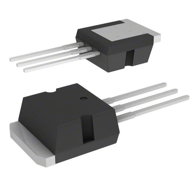
IRFBC40L N-Channel MOSFET 600V 6.2A Equivalent & Substitute Parts
Part Overview
The IRFBC40L is an N-Channel MOSFET manufactured by Vishay Siliconix, rated for 600V drain-to-source voltage with 6.2A continuous drain current. The device is packaged in a Through Hole I2PAK (TO-262-3) configuration and is designed for high-voltage switching applications. The IRFBC40L is classified as obsolete, making identification of equivalent and substitute parts necessary for ongoing design support, maintenance, and new production requirements. Substitute parts must maintain electrical compatibility across critical parameters including voltage rating, current capacity, on-resistance, and thermal characteristics while accommodating packaging and compliance variations.
Substiute Parts
Key Parameters
| Parameter | Value | Unit |
|---|---|---|
| FET Type | N-Channel | — |
| Drain to Source Voltage (Vdss) | 600 | V |
| Current - Continuous Drain (Id) @ 25°C | 6.2 | A (Tc) |
| Rds On (Max) @ Id, Vgs | 1.2 | Ohm @ 3.7A, 10V |
| Vgs(th) (Max) @ Id | 4 | V @ 250µA |
| Gate Charge (Qg) (Max) @ Vgs | 60 | nC @ 10V |
| Vgs (Max) | ±20 | V |
| Input Capacitance (Ciss) (Max) @ Vds | 1300 | pF @ 25V |
| Power Dissipation (Max) | 3.1 (Ta), 130 (Tc) | W |
| Operating Temperature | -55 to 150 | °C (TJ) |
| Mounting Type | Through Hole | — |
| Package / Case | TO-262-3 Long Leads, I2PAK, TO-262AA | — |
Substitute Part Grouping Explanation
Substitute parts for the IRFBC40L are classified based on electrical parameter compatibility and packaging equivalence. The substitution logic is determined by the following critical parameters:
Voltage Rating Compatibility: All substitute parts must maintain a Drain to Source Voltage (Vdss) rating of 600V or higher to ensure safe operation in the original application circuit.
Current Rating Compatibility: Substitute parts must support continuous drain current (Id) at or above 6.2A to handle the same load conditions. Parts with higher current ratings (7.4A, 7.5A) provide additional design margin.
On-Resistance (Rds On) Compatibility: The maximum on-resistance must not exceed the original specification to prevent excessive power dissipation and thermal stress. Equivalent or lower on-resistance values are acceptable.
Gate Threshold Voltage (Vgs(th)) Compatibility: Threshold voltage must remain within acceptable switching control ranges. Values between 4V and 5V are compatible with standard gate drive circuits.
Thermal and Power Dissipation Compatibility: Power dissipation ratings must support the thermal requirements of the application. Higher power dissipation ratings provide additional thermal margin.
Packaging Compatibility: All substitute parts use Through Hole mounting in I2PAK (TO-262-3) or equivalent configurations, ensuring mechanical and electrical compatibility with existing PCB layouts.
Compliance Status: Product status (Active vs. Obsolete) and RoHS compliance determine long-term availability and regulatory suitability for new designs.
Parameter Comparison
| Parameter | IRFBC40L | IRFBC40LPBF | FQI7N60TU | FQI8N60CTU | STI4N62K3 |
|---|---|---|---|---|---|
| Manufacturer | Vishay Siliconix | Vishay Siliconix | Fairchild Semiconductor | Fairchild Semiconductor | STMicroelectronics |
| FET Type | N-Channel | N-Channel | N-Channel | N-Channel | N-Channel |
| Vdss (V) | 600 | 600 | 600 | 600 | 620 |
| Id @ 25°C (A) | 6.2 | 6.2 | 7.4 | 7.5 | 3.8 |
| Rds On (Max) @ Vgs 10V (Ohm) | 1.2 @ 3.7A | 1.2 @ 3.7A | 1.0 @ 3.7A | 1.2 @ 3.75A | 2.0 @ 1.9A |
| Vgs(th) (Max) @ 250µA (V) | 4 | 4 | 5 | 4 | 4.5 |
| Gate Charge (Qg) @ 10V (nC) | 60 | 60 | 38 | 36 | 22 |
| Vgs (Max) (V) | ±20 | ±20 | ±30 | ±30 | ±30 |
| Ciss (Max) @ 25V (pF) | 1300 | 1300 | 1430 | 1255 | 550 |
| Power Dissipation (Tc) (W) | 130 | 130 | 142 | 147 | 70 |
| Operating Temperature (°C) | -55 to 150 | -55 to 150 | -55 to 150 | -55 to 150 | -55 to 150 |
| Mounting Type | Through Hole | Through Hole | Through Hole | Through Hole | Through Hole |
| Package | I2PAK (TO-262-3) | TO-262-3 | I2PAK (TO-262) | I2PAK (TO-262) | I2PAK (TO-262-3) |
| Product Status | Obsolete | Active | Active | Active | Active |
| RoHS Compliance | Non-compliant | ROHS3 Compliant | Not specified | Not specified | ROHS3 Compliant |
Engineering Selection Recommendations
Primary Equivalent: IRFBC40LPBF
The IRFBC40LPBF is the direct parametric equivalent to the IRFBC40L, manufactured by the same supplier (Vishay Siliconix) with identical electrical specifications. This part maintains 600V Vdss, 6.2A continuous drain current, 1.2Ohm Rds On, and all other critical parameters. The IRFBC40LPBF is classified as Active product status, ensuring ongoing availability and supply chain support. The part is ROHS3 compliant, meeting current regulatory requirements for new designs and production. The primary difference is packaging format (Tube vs. unspecified for original), which does not affect electrical or mechanical compatibility. This part is the recommended first choice for direct replacement in existing designs.
Secondary Equivalent: FQI8N60CTU
The FQI8N60CTU, manufactured by Fairchild Semiconductor, provides electrical compatibility with slightly enhanced performance characteristics. This part maintains 600V Vdss and supports 7.5A continuous drain current, exceeding the original 6.2A specification. The Rds On specification of 1.2Ohm @ 3.75A matches the original part's on-resistance profile. Gate charge is reduced to 36nC, improving switching efficiency. Power dissipation is rated at 147W (Tc), providing additional thermal margin over the original 130W specification. The FQI8N60CTU is Active product status with I2PAK (TO-262) packaging, ensuring mechanical compatibility. This part is suitable for applications requiring enhanced current capacity or improved thermal performance.
Secondary Equivalent: FQI7N60TU
The FQI7N60TU, also manufactured by Fairchild Semiconductor, offers improved on-resistance performance at 1.0Ohm @ 3.7A, lower than the original 1.2Ohm specification. This part supports 7.4A continuous drain current and maintains 600V Vdss. Gate charge is significantly reduced to 38nC, enhancing switching speed and reducing drive circuit losses. Power dissipation is rated at 142W (Tc). The FQI7N60TU is Active product status with I2PAK (TO-262) packaging. This part is suitable for applications prioritizing reduced on-resistance and improved switching efficiency.
Alternative Substitute: STI4N62K3
The STI4N62K3, manufactured by STMicroelectronics, provides a higher voltage rating of 620V Vdss, exceeding the original 600V specification. However, this part supports only 3.8A continuous drain current, which is below the original 6.2A specification. The on-resistance is 2.0Ohm @ 1.9A, significantly higher than the original specification. Gate charge is substantially reduced to 22nC. Power dissipation is rated at 70W (Tc), lower than the original 130W specification. The STI4N62K3 is Active product status and ROHS3 compliant with I2PAK packaging. This part is suitable only for applications with reduced current requirements and is not recommended as a direct replacement for the IRFBC40L in high-current switching circuits.
Frequently Asked Questions (FAQ)
Q: Can the IRFBC40LPBF be used as a direct replacement for the IRFBC40L?
A: Yes. The IRFBC40LPBF is a direct parametric equivalent with identical electrical specifications including 600V Vdss, 6.2A continuous drain current, 1.2Ohm Rds On, and operating temperature range. Both parts use Through Hole I2PAK (TO-262-3) packaging. The primary difference is product status (Active vs. Obsolete) and RoHS compliance (ROHS3 vs. Non-compliant), making the IRFBC40LPBF the preferred choice for new designs and ongoing production.
Q: What is the difference between the FQI7N60TU and FQI8N60CTU?
A: Both parts are manufactured by Fairchild Semiconductor and maintain 600V Vdss. The FQI7N60TU supports 7.4A continuous drain current with 1.0Ohm Rds On and 38nC gate charge. The FQI8N60CTU supports 7.5A continuous drain current with 1.2Ohm Rds On and 36nC gate charge. The FQI7N60TU offers lower on-resistance, while the FQI8N60CTU provides slightly higher current capacity. Both are compatible with the original IRFBC40L application.
Q: Why is the STI4N62K3 not recommended as a primary substitute?
A: The STI4N62K3 has a continuous drain current rating of only 3.8A, which is significantly below the original IRFBC40L specification of 6.2A. Additionally, the on-resistance is 2.0Ohm, substantially higher than the original 1.2Ohm specification. This part is suitable only for applications with reduced current requirements and cannot reliably handle the same load conditions as the original part.
Q: Are all substitute parts compatible with the original PCB layout?
A: Yes. All substitute parts listed use Through Hole mounting in I2PAK (TO-262-3) or equivalent I2PAK (TO-262) configurations. These packages are mechanically and electrically compatible with existing PCB layouts designed for the IRFBC40L. No PCB modifications are required for substitution.
Q: What is the significance of gate charge (Qg) differences between substitute parts?
A: Gate charge determines the energy required to switch the MOSFET on and off. Lower gate charge values (FQI7N60TU at 38nC, FQI8N60CTU at 36nC, STI4N62K3 at 22nC) reduce drive circuit losses and improve switching speed compared to the original IRFBC40L at 60nC. This is beneficial for high-frequency switching applications but does not affect compatibility with standard gate drive circuits.
Q: Can substitute parts with higher Vdss ratings be used in place of the IRFBC40L?
A: Yes. The STI4N62K3 with 620V Vdss can be used in applications designed for 600V operation. Higher voltage ratings provide additional safety margin and do not compromise circuit functionality. However, the STI4N62K3's reduced current capacity (3.8A vs. 6.2A) and increased on-resistance (2.0Ohm vs. 1.2Ohm) make it unsuitable for high-current applications.
Q: What compliance considerations apply to substitute part selection?
A: The IRFBC40L is RoHS non-compliant and obsolete. For new designs and production requiring regulatory compliance, the IRFBC40LPBF (ROHS3 compliant, Active status) or STI4N62K3 (ROHS3 compliant, Active status) are recommended. Fairchild Semiconductor parts (FQI7N60TU, FQI8N60CTU) do not specify RoHS compliance status in the provided data.
Q: How do input capacitance (Ciss) differences affect circuit design?
A: Input capacitance affects gate drive circuit design and switching transient behavior. The original IRFBC40L has 1300pF Ciss. Substitute parts range from 550pF (STI4N62K3) to 1430pF (FQI7N60TU). Lower capacitance values reduce gate drive current requirements and improve switching speed. Higher capacitance values require more gate drive current but do not prevent substitution in standard applications.
Alternative Parts

SJ6012L2TP
Littelfuse Inc.
6 Alternative Parts

JMK107BBJ476MA-RE
Taiyo Yuden
10 Alternative Parts

GMK107BBJ475MA-T
Taiyo Yuden
5 Alternative Parts
SJ6020N2ARP
Littelfuse Inc.
3 Alternative Parts
SJ6025R2ATP
Littelfuse Inc.
4 Alternative Parts

2474-05L
API Delevan Inc.
1 Alternative Parts

4590R-684K
API Delevan Inc.
1 Alternative Parts

CM6560R-334
API Delevan Inc.
1 Alternative Parts

CM6460-104
API Delevan Inc.
1 Alternative Parts

5526-12
API Delevan Inc.
1 Alternative Parts