


Request Quote
(Ships tomorrow)
IRF840LPBF Equivalent & Substitute Parts
Part Overview
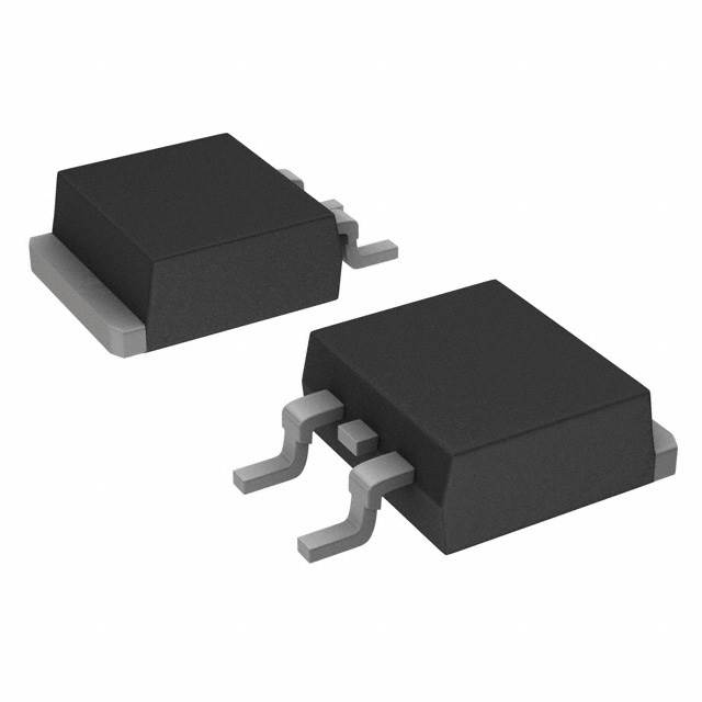
The IRF840LPBF is an N-Channel MOSFET manufactured by Vishay Siliconix, rated for 500V drain-to-source voltage with 8A continuous drain current at 25°C. The device is packaged in a surface mount TO-263 (D2PAK) configuration and is currently in active product status. This component is commonly used in switching applications, power conversion circuits, and high-voltage switching topologies where reliable N-Channel MOSFET performance is required.
Substitute parts become necessary when the IRF840LPBF is unavailable from inventory, when alternative packaging formats are required for specific board layouts, or when design modifications necessitate different electrical characteristics within the 500V class of N-Channel MOSFETs.
Substiute Parts
Key Parameters
| Parameter | Value | Unit |
|---|---|---|
| FET Type | N-Channel | — |
| Drain to Source Voltage (Vdss) | 500 | V |
| Current - Continuous Drain (Id) @ 25°C | 8 | A (Tc) |
| Drive Voltage (Max Rds On) | 10 | V |
| Rds On (Max) @ Id, Vgs | 850 | mOhm @ 4.8A, 10V |
| Power Dissipation (Max) | 125 | W (Tc) |
| Operating Temperature Range | -55 to 150 | °C (TJ) |
| Mounting Type | Surface Mount | — |
| Package | TO-263-3 (D2PAK) | — |
| RoHS Status | ROHS3 Compliant | — |
Substitute Part Grouping Explanation
Substitution of the IRF840LPBF is determined by strict adherence to the following electrical and mechanical parameters:
Critical Substitution Criteria:
- Drain to Source Voltage (Vdss): Must equal 500V
- FET Type: Must be N-Channel
- Technology: Must be MOSFET (Metal Oxide)
- Drive Voltage: Must be rated at 10V for Rds On specification
- Operating Temperature Range: Must support -55°C to 150°C minimum
- RoHS Compliance: Must be ROHS3 Compliant
Allowable Variations:
- Continuous Drain Current (Id): Substitute parts may have lower current ratings (7.2A, 7A, or 5A) provided the application does not exceed the substitute part's rating
- Rds On (Max): Substitute parts may have lower on-resistance values
- Power Dissipation: Substitute parts may have lower power dissipation ratings
- Mounting Type: Substitute parts may use different mounting configurations (surface mount or through hole)
- Package Type: Substitute parts may use different package formats (TO-220 vs. TO-263)
- Gate Charge and Input Capacitance: Substitute parts may have different values
All substitute parts listed meet the core voltage, current class, and compliance requirements for direct functional substitution within the specified parameter envelope.
Parameter Comparison
| Parameter | IRF840LPBF (Main) | FDP7N50 | STP8NM50N | STP9NK50Z |
|---|---|---|---|---|
| Manufacturer | Vishay Siliconix | onsemi | STMicroelectronics | STMicroelectronics |
| FET Type | N-Channel | N-Channel | N-Channel | N-Channel |
| Drain to Source Voltage (Vdss) | 500 V | 500 V | 500 V | 500 V |
| Current - Continuous Drain (Id) @ 25°C | 8 A (Tc) | 7 A (Tc) | 5 A (Tc) | 7.2 A (Tc) |
| Drive Voltage (Max Rds On) | 10 V | 10 V | 10 V | 10 V |
| Rds On (Max) @ Id, Vgs | 850 mOhm @ 4.8A, 10V | 900 mOhm @ 3.5A, 10V | 790 mOhm @ 2.5A, 10V | 850 mOhm @ 3.6A, 10V |
| Vgs(th) (Max) @ Id | 4 V @ 250µA | 5 V @ 250µA | 4 V @ 250µA | 4.5 V @ 100µA |
| Gate Charge (Qg) (Max) @ Vgs | 63 nC @ 10 V | 16.6 nC @ 10 V | 14 nC @ 10 V | 32 nC @ 10 V |
| Vgs (Max) | ±20 V | ±30 V | ±25 V | ±30 V |
| Input Capacitance (Ciss) (Max) @ Vds | 1300 pF @ 25 V | 940 pF @ 25 V | 364 pF @ 50 V | 910 pF @ 25 V |
| Power Dissipation (Max) | 125 W (Tc) | 89 W (Tc) | 45 W (Tc) | 110 W (Tc) |
| Operating Temperature Range | -55°C ~ 150°C (TJ) | -55°C ~ 150°C (TJ) | -55°C ~ 150°C (TJ) | -55°C ~ 150°C (TJ) |
| Mounting Type | Surface Mount | Through Hole | Through Hole | Through Hole |
| Package / Case | TO-263-3 (D2PAK) | TO-220-3 | TO-220-3 | TO-220-3 |
| Product Status | Active | Obsolete | Active | Active |
| RoHS Status | ROHS3 Compliant | ROHS3 Compliant | ROHS3 Compliant | ROHS3 Compliant |
Engineering Selection Recommendations
STP9NK50Z (STMicroelectronics) - Primary Substitute
The STP9NK50Z is the preferred substitute for the IRF840LPBF when through-hole TO-220 packaging is acceptable. This device maintains active product status, meets all RoHS3 compliance requirements, and provides 7.2A continuous drain current with 110W power dissipation. The electrical characteristics closely match the IRF840LPBF, with identical 500V Vdss rating and 10V drive voltage specification. The STP9NK50Z is available in high inventory (15,942 units), ensuring supply continuity. The primary design consideration is the transition from surface mount TO-263 to through-hole TO-220 packaging, which requires PCB layout modification.
STP8NM50N (STMicroelectronics) - Secondary Substitute
The STP8NM50N serves as an alternative when lower power dissipation or reduced gate charge is required. This device is active in product status and ROHS3 compliant. The 5A continuous drain current rating is lower than the IRF840LPBF, limiting its use to applications where the design current does not exceed 5A. The STP8NM50N offers superior on-resistance characteristics (790 mOhm) and significantly lower input capacitance (364 pF), making it suitable for high-frequency switching applications. Through-hole TO-220 packaging applies.
FDP7N50 (onsemi) - Not Recommended
The FDP7N50 is marked as obsolete product status and should not be selected for new designs or long-term supply assurance. Although it meets the 500V Vdss and 10V drive voltage requirements with 7A continuous drain current, the obsolete classification presents supply risk and potential future unavailability.
Frequently Asked Questions (FAQ)
Q: Can the IRF840LPBF be directly replaced with the STP9NK50Z without circuit modification?
A: Electrical substitution is direct; however, packaging differs. The IRF840LPBF uses surface mount TO-263 (D2PAK), while the STP9NK50Z uses through-hole TO-220. PCB layout and mounting hardware must be modified accordingly. All electrical parameters remain compatible within the specified operating envelope.
Q: What is the primary limitation of the STP8NM50N as a substitute?
A: The STP8NM50N has a maximum continuous drain current of 5A, compared to the IRF840LPBF's 8A rating. Applications requiring sustained current above 5A cannot use this substitute. Verify application current requirements before selection.
Q: Why is the FDP7N50 listed if it is obsolete?
A: The FDP7N50 is included in the substitute list for reference purposes only, documenting historical equivalency. For new designs and procurement, the FDP7N50 should not be selected due to obsolete product status and associated supply discontinuation risk.
Q: Are all substitute parts RoHS3 compliant?
A: Yes. The IRF840LPBF and all listed substitute parts (STP9NK50Z, STP8NM50N, and FDP7N50) are ROHS3 compliant, meeting environmental and regulatory requirements for lead-free manufacturing.
Q: What is the impact of different gate charge values on circuit design?
A: Gate charge (Qg) affects gate drive circuit design and switching speed. The IRF840LPBF has 63 nC gate charge, while substitutes range from 14 nC to 32 nC. Lower gate charge reduces drive circuit power consumption and enables faster switching. Gate drive circuits must be verified to ensure adequate charge delivery at the specified drive voltage.
Q: Can the IRF840LPBF be used in applications designed for the STP9NK50Z?
A: Yes, with design margin verification. The IRF840LPBF provides higher continuous drain current (8A vs. 7.2A) and greater power dissipation capability (125W vs. 110W). However, the higher gate charge (63 nC vs. 32 nC) requires gate drive circuit confirmation. Surface mount packaging differs from through-hole, requiring PCB redesign.
Q: What operating temperature range applies to all substitute parts?
A: All substitute parts support the full -55°C to 150°C junction temperature range, matching the IRF840LPBF specification. Thermal management design must account for the specific power dissipation rating of the selected substitute.
Alternative Parts

SJ6012L2TP
Littelfuse Inc.
6 Alternative Parts

JMK107BBJ476MA-RE
Taiyo Yuden
10 Alternative Parts

GMK107BBJ475MA-T
Taiyo Yuden
5 Alternative Parts
SJ6020N2ARP
Littelfuse Inc.
3 Alternative Parts
SJ6025R2ATP
Littelfuse Inc.
4 Alternative Parts

2474-05L
API Delevan Inc.
1 Alternative Parts

4590R-684K
API Delevan Inc.
1 Alternative Parts

CM6560R-334
API Delevan Inc.
1 Alternative Parts

CM6460-104
API Delevan Inc.
1 Alternative Parts

5526-12
API Delevan Inc.
1 Alternative Parts