


Request Quote
(Ships tomorrow)
IRF7663 Equivalent & Substitute Parts
Part Overview
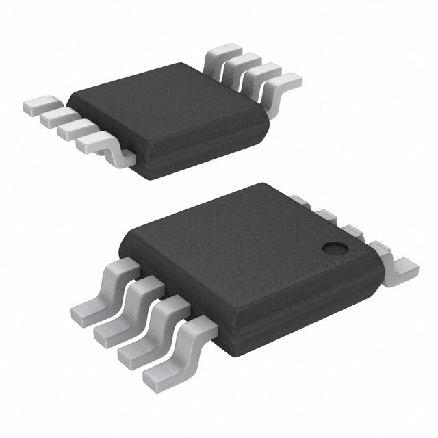
The IRF7663 is a P-Channel MOSFET manufactured by Infineon Technologies, rated for 20V drain-to-source voltage with 8.2A continuous drain current at 25°C. This device is packaged in the Micro8™ (8-TSSOP/8-MSOP) surface mount configuration and is designed for applications requiring P-channel switching and amplification in compact form factors.
The IRF7663 is classified as obsolete. Identifying equivalent substitute parts is necessary to maintain design continuity, ensure supply chain availability, and support ongoing production requirements for applications currently utilizing this component.
Substiute Parts
Key Parameters
| Parameter | Value | Unit |
|---|---|---|
| FET Type | P-Channel | — |
| Drain-to-Source Voltage (Vdss) | 20 | V |
| Continuous Drain Current (Id) @ 25°C | 8.2 | A |
| On-Resistance (Rds On Max) @ Id, Vgs | 20 mOhm @ 7A, 4.5V | — |
| Gate Threshold Voltage (Vgs(th) Max) @ Id | 1.2 | V @ 250µA |
| Gate Charge (Qg Max) @ Vgs | 45 | nC @ 5V |
| Input Capacitance (Ciss Max) @ Vds | 2520 | pF @ 10V |
| Power Dissipation (Max) | 1.8 | W |
| Package Type | 8-TSSOP, 8-MSOP (0.118", 3.00mm Width) | — |
| Mounting Type | Surface Mount | — |
Substitute Part Grouping Explanation
Substitution of the IRF7663 is determined by the following critical electrical and mechanical parameters:
Electrical Compatibility Criteria:
- FET Type: P-Channel topology must be maintained
- Drain-to-Source Voltage (Vdss): Minimum 20V rating required
- Continuous Drain Current (Id): Minimum 3.5A acceptable for applications with reduced current requirements
- On-Resistance (Rds On): Lower values preferred; higher values acceptable if within application thermal budget
- Gate Threshold Voltage (Vgs(th)): Must be compatible with available gate drive voltage
- Gate Charge (Qg): Lower values reduce switching losses and gate drive requirements
- Input Capacitance (Ciss): Lower values improve switching speed
Mechanical Compatibility Criteria:
- Package Type: 8-TSSOP or 8-MSOP with 0.118" (3.00mm) width for PCB layout compatibility
- Mounting Type: Surface Mount configuration required
The ZXM64P02XTA from Diodes Incorporated meets these substitution criteria. While it exhibits lower continuous drain current (3.5A versus 8.2A) and higher on-resistance (90 mOhm versus 20 mOhm), it maintains the same voltage rating, package footprint, and surface mount configuration. This substitute is suitable for applications where the reduced current rating does not exceed design requirements.
Parameter Comparison
| Parameter | IRF7663 (Infineon) | ZXM64P02XTA (Diodes Inc.) | Unit |
|---|---|---|---|
| Manufacturer | Infineon Technologies | Diodes Incorporated | — |
| Product Status | Obsolete | Active | — |
| FET Type | P-Channel | P-Channel | — |
| Drain-to-Source Voltage (Vdss) | 20 | 20 | V |
| Continuous Drain Current (Id) @ 25°C | 8.2 | 3.5 | A |
| On-Resistance (Rds On Max) | 20 mOhm @ 7A, 4.5V | 90 mOhm @ 2.4A, 4.5V | — |
| Gate Threshold Voltage (Vgs(th) Max) | 1.2 @ 250µA | 0.7 @ 250µA | V |
| Gate Charge (Qg Max) | 45 @ 5V | 6.9 @ 4.5V | nC |
| Input Capacitance (Ciss Max) | 2520 @ 10V | 900 @ 15V | pF |
| Power Dissipation (Max) | 1.8 | 1.1 | W |
| Package Type | 8-TSSOP, 8-MSOP | 8-TSSOP, 8-MSOP | — |
| Mounting Type | Surface Mount | Surface Mount | — |
| RoHS Status | RoHS non-compliant | ROHS3 Compliant | — |
| Moisture Sensitivity Level (MSL) | 1 (Unlimited) | 1 (Unlimited) | — |
Engineering Selection Recommendations
IRF7663 (Infineon Technologies): The IRF7663 is obsolete and no longer in active production. New designs should not incorporate this part number. Existing applications using the IRF7663 require substitution planning to ensure continued supply and support.
ZXM64P02XTA (Diodes Incorporated): The ZXM64P02XTA is an active product with ROHS3 compliance, providing regulatory advantage over the obsolete IRF7663. This substitute maintains identical voltage rating (20V) and package footprint (8-TSSOP/8-MSOP), enabling direct PCB layout compatibility.
Selection Criteria:
- Use ZXM64P02XTA for new designs and production transitions from IRF7663
- Verify application current requirements do not exceed 3.5A continuous drain current
- Account for higher on-resistance (90 mOhm) in thermal calculations; power dissipation will increase proportionally with current
- Confirm gate drive voltage compatibility; ZXM64P02XTA has lower gate threshold voltage (0.7V minimum versus 1.2V maximum for IRF7663)
- Evaluate switching frequency impact; lower gate charge (6.9 nC) and input capacitance (900 pF) of ZXM64P02XTA reduce switching losses
Frequently Asked Questions (FAQ)
Q: Can the ZXM64P02XTA directly replace the IRF7663 in existing designs?
A: Direct PCB replacement is possible due to identical package footprint (8-TSSOP/8-MSOP, 0.118" width). However, functional compatibility depends on application current requirements. The ZXM64P02XTA is rated for 3.5A continuous drain current versus 8.2A for the IRF7663. If the application requires sustained current above 3.5A, the substitute is not suitable. Additionally, the higher on-resistance (90 mOhm versus 20 mOhm) will increase power dissipation and heat generation.
Q: What are the key electrical differences between these parts?
A: The primary differences are continuous drain current (8.2A versus 3.5A), on-resistance (20 mOhm versus 90 mOhm), gate charge (45 nC versus 6.9 nC), and input capacitance (2520 pF versus 900 pF). Both maintain 20V voltage rating and P-channel topology. The ZXM64P02XTA exhibits lower gate charge and capacitance, resulting in faster switching characteristics and reduced gate drive power requirements.
Q: Are there thermal considerations when substituting to ZXM64P02XTA?
A: Yes. The higher on-resistance of the ZXM64P02XTA results in greater power dissipation at equivalent current levels. Thermal analysis must account for increased junction temperature rise. If the application operates near the IRF7663's current rating, the substitute may exceed thermal limits. Verify that the application's actual operating current remains within the ZXM64P02XTA's 3.5A rating to maintain acceptable thermal performance.
Q: What is the compliance advantage of ZXM64P02XTA?
A: The ZXM64P02XTA is ROHS3 compliant, whereas the IRF7663 is RoHS non-compliant. For applications subject to RoHS regulations or customer requirements, the ZXM64P02XTA provides regulatory compliance. Both parts are REACH Unaffected and classified as EAR99 for export control purposes.
Q: Are there gate drive voltage differences?
A: The ZXM64P02XTA has a lower gate threshold voltage (0.7V minimum @ 250µA) compared to the IRF7663 (1.2V maximum @ 250µA). This allows the substitute to turn on at lower gate voltages, potentially improving compatibility with lower-voltage gate drive circuits. Verify that the application's gate drive voltage is sufficient to fully enhance the ZXM64P02XTA for proper on-state performance.
Q: What packaging considerations apply to this substitution?
A: Both parts use identical 8-TSSOP/8-MSOP surface mount packages with 0.118" (3.00mm) width. PCB footprints are compatible without modification. The ZXM64P02XTA is supplied in Tape & Reel (TR) packaging, standard for production environments. Moisture sensitivity level is identical (MSL 1, Unlimited) for both parts, requiring no change in handling or storage procedures.
Alternative Parts

SJ6012L2TP
Littelfuse Inc.
6 Alternative Parts

JMK107BBJ476MA-RE
Taiyo Yuden
10 Alternative Parts

GMK107BBJ475MA-T
Taiyo Yuden
5 Alternative Parts
SJ6020N2ARP
Littelfuse Inc.
3 Alternative Parts
SJ6025R2ATP
Littelfuse Inc.
4 Alternative Parts

2474-05L
API Delevan Inc.
1 Alternative Parts

4590R-684K
API Delevan Inc.
1 Alternative Parts

CM6560R-334
API Delevan Inc.
1 Alternative Parts

CM6460-104
API Delevan Inc.
1 Alternative Parts

5526-12
API Delevan Inc.
1 Alternative Parts