


Request Quote
(Ships tomorrow)
IRF720STRR Equivalent & Substitute Parts
Part Overview
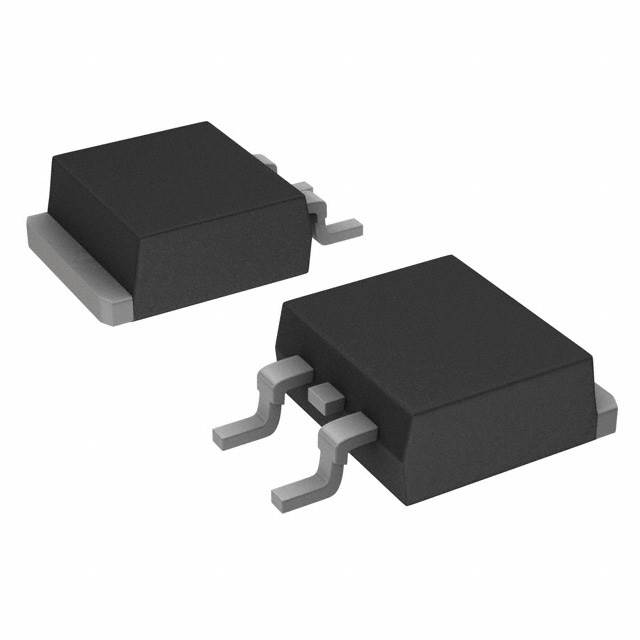
The IRF720STRR is an N-Channel MOSFET manufactured by Vishay Siliconix, rated for 400V drain-to-source voltage with 3.3A continuous drain current. The device is housed in a Surface Mount TO-263 (D2PAK) package and is classified as obsolete. Due to its obsolete product status, equivalent and substitute parts with active availability are necessary for ongoing design support and production continuity.
Substiute Parts
Key Parameters
| Parameter | Value | Unit |
|---|---|---|
| Drain to Source Voltage (Vdss) | 400 | V |
| Continuous Drain Current (Id) @ 25°C | 3.3 | A (Tc) |
| On-State Resistance (Rds On) @ 2A, 10V | 1.8 | Ohm |
| Gate Threshold Voltage (Vgs(th)) @ 250µA | 4 | V |
| Gate Charge (Qg) @ 10V | 20 | nC |
| Power Dissipation (Max) | 3.1 (Ta), 50 (Tc) | W |
| Operating Temperature Range | -55 to 150 | °C (TJ) |
| Package Type | TO-263 (D2PAK) | Surface Mount |
Substitute Part Grouping Explanation
Substitution of the IRF720STRR is determined by the following critical parameters: drain-to-source voltage rating (Vdss), continuous drain current capability (Id), on-state resistance (Rds On), gate threshold voltage (Vgs(th)), and package compatibility. The substitute parts are grouped based on electrical parameter equivalence and product availability status.
Parametric Equivalent (Direct Replacement): IRF720STRRPBF maintains identical electrical specifications and package configuration as the IRF720STRR, with the primary distinction being active product status and RoHS3 compliance.
Manufacturer Recommended Substitute: IRF540NSTRLPBF is listed as a manufacturer-recommended alternative. This part operates at a lower voltage rating (100V Vdss) but provides significantly higher current capability (33A Id) and lower on-state resistance (44mOhm). This substitution is applicable only in applications where the 100V voltage rating is sufficient for the circuit design.
Parameter Comparison
| Parameter | IRF720STRR | IRF720STRRPBF | IRF540NSTRLPBF | Unit |
|---|---|---|---|---|
| Manufacturer | Vishay Siliconix | Vishay Siliconix | Infineon Technologies | — |
| FET Type | N-Channel | N-Channel | N-Channel | — |
| Drain to Source Voltage (Vdss) | 400 | 400 | 100 | V |
| Continuous Drain Current (Id) @ 25°C | 3.3 | 3.3 | 33 | A (Tc) |
| On-State Resistance (Rds On) @ 10V | 1.8 @ 2A | 1.8 @ 2A | 0.044 @ 16A | Ohm |
| Gate Threshold Voltage (Vgs(th)) @ 250µA | 4 | 4 | 4 | V |
| Gate Charge (Qg) @ 10V | 20 | 20 | 71 | nC |
| Input Capacitance (Ciss) @ 25V | 410 | 410 | 1960 | pF |
| Power Dissipation (Max) | 3.1 (Ta), 50 (Tc) | 3.1 (Ta), 50 (Tc) | 130 (Tc) | W |
| Operating Temperature Range | -55 to 150 | -55 to 150 | -55 to 175 | °C (TJ) |
| Package Type | TO-263 (D2PAK) | TO-263 (D2PAK) | TO-263 (D2PAK) | Surface Mount |
| Product Status | Obsolete | Active | Active | — |
| RoHS Status | Non-compliant | ROHS3 Compliant | ROHS3 Compliant | — |
| Inventory Availability | 1036 Pcs | 2100 Pcs | 35300 Pcs | — |
Engineering Selection Recommendations
For Direct Replacement (Identical Electrical Performance): The IRF720STRRPBF is the appropriate selection when maintaining the exact electrical specifications of the IRF720STRR is required. This part is manufactured by the same supplier (Vishay Siliconix), maintains all electrical parameters, and is available in active product status with ROHS3 compliance. Inventory availability is higher (2100 Pcs) compared to the obsolete IRF720STRR.
For Voltage-Reduced Applications: The IRF540NSTRLPBF may be selected only in applications where the circuit design operates at voltages not exceeding 100V. This part provides superior current handling (33A versus 3.3A) and significantly lower on-state resistance (44mOhm versus 1.8Ohm), resulting in reduced power dissipation. The IRF540NSTRLPBF is manufactured by Infineon Technologies and carries ROHS3 compliance with substantially higher inventory availability (35300 Pcs). The increased gate charge (71nC versus 20nC) and input capacitance (1960pF versus 410pF) must be evaluated for gate drive circuit compatibility.
Compliance Considerations: Both substitute parts are ROHS3 compliant, whereas the original IRF720STRR is non-compliant. The IRF720STRRPBF maintains identical moisture sensitivity level (MSL 1) and REACH unaffected status.
Frequently Asked Questions (FAQ)
Q: Can the IRF720STRRPBF be used as a direct replacement for the IRF720STRR?
A: Yes. The IRF720STRRPBF is electrically and mechanically identical to the IRF720STRR. Both parts share the same drain-to-source voltage (400V), continuous drain current (3.3A), on-state resistance (1.8Ohm @ 2A, 10V), and TO-263 (D2PAK) package configuration. The primary differences are product status (active versus obsolete) and RoHS compliance (ROHS3 versus non-compliant).
Q: Under what conditions can the IRF540NSTRLPBF substitute for the IRF720STRR?
A: The IRF540NSTRLPBF can substitute only in applications where the maximum circuit voltage does not exceed 100V. The IRF720STRR is rated for 400V operation, while the IRF540NSTRLPBF is rated for 100V. Exceeding the 100V rating of the IRF540NSTRLPBF will result in device failure. Applications operating at or below 100V benefit from the IRF540NSTRLPBF's superior current handling and lower on-state resistance.
Q: Are all substitute parts compatible with the same PCB footprint?
A: Yes. All three parts (IRF720STRR, IRF720STRRPBF, and IRF540NSTRLPBF) use the TO-263 (D2PAK) package with identical pin configuration and footprint. No PCB layout modifications are required for mechanical compatibility.
Q: What is the impact of the higher gate charge in the IRF540NSTRLPBF?
A: The IRF540NSTRLPBF has a gate charge of 71nC compared to 20nC in the IRF720STRR. Higher gate charge requires greater charge delivery from the gate drive circuit, potentially increasing switching losses and requiring a more robust gate driver. The gate drive circuit must be evaluated to confirm adequate current sourcing and sinking capability.
Q: What is the significance of the higher input capacitance in the IRF540NSTRLPBF?
A: The IRF540NSTRLPBF has an input capacitance of 1960pF compared to 410pF in the IRF720STRR. Higher input capacitance increases the capacitive load on the gate drive circuit, which may affect switching speed and gate drive power dissipation. Gate drive circuit design must account for this increased capacitive load.
Q: Is the IRF720STRRPBF available in the same packaging format as the IRF720STRR?
A: Yes. The IRF720STRRPBF is supplied in Tape & Reel (TR) packaging, identical to the IRF720STRR. Both parts are Surface Mount devices in TO-263 (D2PAK) configuration.
Q: What is the difference in operating temperature range between the substitute parts?
A: The IRF720STRR and IRF720STRRPBF both operate from -55°C to 150°C (TJ). The IRF540NSTRLPBF extends the upper operating temperature to 175°C (TJ), providing a 25°C higher maximum junction temperature rating. This difference is relevant only in high-temperature applications.
Alternative Parts

SJ6012L2TP
Littelfuse Inc.
6 Alternative Parts

JMK107BBJ476MA-RE
Taiyo Yuden
10 Alternative Parts

GMK107BBJ475MA-T
Taiyo Yuden
5 Alternative Parts
SJ6020N2ARP
Littelfuse Inc.
3 Alternative Parts
SJ6025R2ATP
Littelfuse Inc.
4 Alternative Parts

2474-05L
API Delevan Inc.
1 Alternative Parts

4590R-684K
API Delevan Inc.
1 Alternative Parts

CM6560R-334
API Delevan Inc.
1 Alternative Parts

CM6460-104
API Delevan Inc.
1 Alternative Parts

5526-12
API Delevan Inc.
1 Alternative Parts