


Request Quote
(Ships tomorrow)
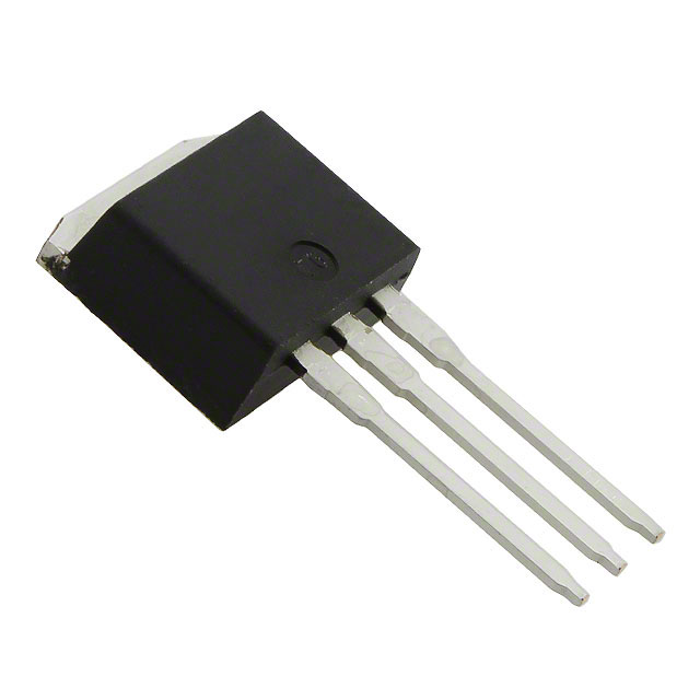
IRF720L N-Channel MOSFET 400V 3.3A Equivalent & Substitute Parts
Part Overview
The IRF720L is an N-Channel MOSFET manufactured by Vishay Siliconix, rated for 400V drain-to-source voltage with a continuous drain current of 3.3A at 25°C. The device is packaged in a Through Hole I2PAK (TO-262-3) configuration and is designed for general-purpose switching applications requiring moderate voltage and current ratings.
The IRF720L is classified as an obsolete product. Identifying equivalent and substitute parts is necessary to maintain design continuity, ensure component availability, and support ongoing production or repair requirements. Substitute parts must maintain electrical compatibility across critical parameters including voltage rating, current capacity, and thermal characteristics.
Substiute Parts
Key Parameters
| Parameter | Value | Unit |
|---|---|---|
| Drain to Source Voltage (Vdss) | 400 | V |
| Continuous Drain Current (Id) @ 25°C | 3.3 | A (Tc) |
| Drive Voltage (Max Rds On) | 10 | V |
| Rds On (Max) @ Id, Vgs | 1.8 | Ohm @ 2A, 10V |
| Gate Threshold Voltage (Vgs(th)) @ Id | 4 | V @ 250µA |
| Gate Charge (Qg) @ Vgs | 20 | nC @ 10V |
| Maximum Gate Voltage (Vgs) | ±20 | V |
| Input Capacitance (Ciss) @ Vds | 410 | pF @ 25V |
| Power Dissipation (Max) | 3.1 (Ta), 50 (Tc) | W |
| Operating Temperature Range | -55 to 150 | °C (TJ) |
| Mounting Type | Through Hole | |
| Package Type | TO-262-3 (I2PAK) | |
| Product Status | Obsolete |
Substitute Part Grouping Explanation
Substitute parts for the IRF720L are identified based on strict electrical and mechanical compatibility criteria. The substitution logic is based on the following key parameters:
Electrical Compatibility Requirements:
- Drain to Source Voltage (Vdss) must equal or exceed 400V
- Continuous Drain Current (Id) must equal or exceed 3.3A at 25°C
- Gate Threshold Voltage (Vgs(th)) must be compatible with existing drive circuits
- Maximum Gate Voltage (Vgs) must accommodate ±20V or greater
- Operating Temperature Range must span -55°C to 150°C
Mechanical Compatibility Requirements:
- Mounting Type: Through Hole
- Package compatibility with TO-262-3 footprint or equivalent pin configuration
Compliance and Status:
- Active product status preferred for long-term availability
- RoHS compliance status noted for regulatory requirements
The IRF720L has two identified substitutes: IRF720LPBF (direct equivalent from same manufacturer) and STP7NK40Z (cross-manufacturer alternative with enhanced specifications).
Parameter Comparison
| Parameter | IRF720L | IRF720LPBF | STP7NK40Z |
|---|---|---|---|
| Manufacturer | Vishay Siliconix | Vishay Siliconix | STMicroelectronics |
| Drain to Source Voltage (Vdss) | 400V | 400V | 400V |
| Continuous Drain Current (Id) @ 25°C | 3.3A (Tc) | 3.3A (Tc) | 5.4A (Tc) |
| Drive Voltage (Max Rds On) | 10V | 10V | 10V |
| Rds On (Max) @ Id, Vgs | 1.8Ω @ 2A, 10V | 1.8Ω @ 2A, 10V | 1Ω @ 2.7A, 10V |
| Gate Threshold Voltage (Vgs(th)) @ Id | 4V @ 250µA | 4V @ 250µA | 4.5V @ 50µA |
| Gate Charge (Qg) @ Vgs | 20nC @ 10V | 20nC @ 10V | 26nC @ 10V |
| Maximum Gate Voltage (Vgs) | ±20V | ±20V | ±30V |
| Input Capacitance (Ciss) @ Vds | 410pF @ 25V | 410pF @ 25V | 535pF @ 25V |
| Power Dissipation (Max) | 3.1W (Ta), 50W (Tc) | 3.1W (Ta), 50W (Tc) | 70W (Tc) |
| Operating Temperature Range | -55°C to 150°C (TJ) | -55°C to 150°C (TJ) | -55°C to 150°C (TJ) |
| Mounting Type | Through Hole | Through Hole | Through Hole |
| Package Type | TO-262-3 (I2PAK) | TO-262-3 | TO-220-3 |
| Product Status | Obsolete | Active | Active |
| RoHS Status | Non-compliant | ROHS3 Compliant | ROHS3 Compliant |
Engineering Selection Recommendations
IRF720LPBF (Vishay Siliconix):
The IRF720LPBF is a direct electrical and functional equivalent to the IRF720L. Both devices share identical electrical specifications including Vdss, Id, Rds On, and thermal characteristics. The primary distinction is product status: IRF720LPBF is classified as Active, ensuring continued availability and manufacturing support. IRF720LPBF is ROHS3 compliant, meeting current regulatory requirements. The package type is TO-262-3, which maintains compatibility with existing PCB layouts designed for the IRF720L. This substitute is recommended for applications requiring direct replacement with minimal design modification.
STP7NK40Z (STMicroelectronics):
The STP7NK40Z is a cross-manufacturer substitute that exceeds the electrical specifications of the IRF720L. The device provides higher continuous drain current (5.4A versus 3.3A), lower on-resistance (1Ω versus 1.8Ω), and greater power dissipation capability (70W versus 50W). The STP7NK40Z is classified as Active with ROHS3 compliance. The package type is TO-220-3, which differs from the IRF720L TO-262-3 footprint and requires PCB layout modification. The STP7NK40Z is suitable for applications where enhanced thermal performance or higher current capacity is beneficial, provided mechanical integration is feasible.
Both substitutes maintain the 400V voltage rating and -55°C to 150°C operating temperature range required for IRF720L replacement. Selection between IRF720LPBF and STP7NK40Z depends on packaging constraints and thermal requirements of the target application.
Frequently Asked Questions (FAQ)
Q: Can IRF720LPBF be used as a direct replacement for IRF720L without PCB modification?
A: Yes. The IRF720LPBF shares identical electrical specifications and is packaged in TO-262-3, which maintains footprint compatibility with the IRF720L. No PCB layout changes are required for this substitution.
Q: What is the primary advantage of using STP7NK40Z over IRF720LPBF?
A: The STP7NK40Z provides enhanced electrical performance with higher continuous drain current (5.4A versus 3.3A), lower on-resistance (1Ω versus 1.8Ω), and greater power dissipation (70W versus 50W). These characteristics reduce thermal stress and improve efficiency in high-current applications. However, the TO-220-3 package requires PCB redesign compared to the TO-262-3 footprint of the IRF720L.
Q: Are both substitute parts RoHS compliant?
A: Yes. Both IRF720LPBF and STP7NK40Z are ROHS3 compliant. The original IRF720L is RoHS non-compliant. Substitution with either part satisfies current RoHS regulatory requirements.
Q: What is the difference between I2PAK and TO-262-3 packaging?
A: I2PAK and TO-262-3 refer to the same package type. I2PAK is the commercial designation, while TO-262-3 is the standardized package code. Both terms describe the same three-lead Through Hole configuration used by the IRF720L and IRF720LPBF.
Q: Can STP7NK40Z be used in applications designed for IRF720L if thermal performance is a concern?
A: Yes, provided mechanical integration is feasible. The STP7NK40Z exceeds all electrical requirements of the IRF720L and provides superior thermal performance. The TO-220-3 package offers better heat dissipation than TO-262-3. PCB layout modification is required to accommodate the different pin configuration and larger package footprint.
Q: What is the significance of the product status (Obsolete vs. Active)?
A: Product status indicates manufacturing and supply availability. The IRF720L is obsolete, meaning Vishay Siliconix no longer manufactures or supports this part. IRF720LPBF and STP7NK40Z are both Active, ensuring continued production, technical support, and long-term availability. Active status is preferred for new designs and ongoing production requirements.
Q: Are the gate threshold voltages of the substitutes compatible with existing drive circuits?
A: The IRF720LPBF has identical gate threshold voltage (4V @ 250µA) to the IRF720L, ensuring full compatibility with existing drive circuits. The STP7NK40Z has a slightly higher threshold voltage (4.5V @ 50µA), which remains within acceptable operating margins for most standard gate driver circuits. Verification of gate drive voltage levels is recommended for applications with marginal drive voltage specifications.
Q: What is the impact of higher input capacitance in STP7NK40Z?
A: The STP7NK40Z has higher input capacitance (535pF versus 410pF), which increases gate charge requirements and may affect switching speed. Applications with high-frequency switching or limited gate drive current should account for this parameter. The higher gate charge (26nC versus 20nC) requires proportionally greater gate drive capability.
Alternative Parts

SJ6012L2TP
Littelfuse Inc.
6 Alternative Parts

JMK107BBJ476MA-RE
Taiyo Yuden
10 Alternative Parts

GMK107BBJ475MA-T
Taiyo Yuden
5 Alternative Parts
SJ6020N2ARP
Littelfuse Inc.
3 Alternative Parts
SJ6025R2ATP
Littelfuse Inc.
4 Alternative Parts

2474-05L
API Delevan Inc.
1 Alternative Parts

4590R-684K
API Delevan Inc.
1 Alternative Parts

CM6560R-334
API Delevan Inc.
1 Alternative Parts

CM6460-104
API Delevan Inc.
1 Alternative Parts

5526-12
API Delevan Inc.
1 Alternative Parts