


Request Quote
(Ships tomorrow)
IRF644L Equivalent & Substitute Parts
Part Overview
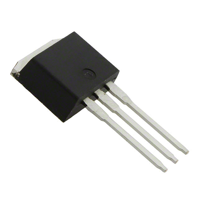
The IRF644L is an N-Channel MOSFET manufactured by Vishay Siliconix, rated for 250V drain-to-source voltage with 14A continuous drain current at 25°C. The device is packaged in I2PAK (TO-262-3 Long Leads) configuration for through-hole mounting. The IRF644L is classified as obsolete, necessitating identification of functionally equivalent substitute components for new designs and ongoing production requirements. Substitute parts must maintain electrical compatibility across voltage, current, and thermal operating ranges while accommodating packaging and compliance requirements.
Substiute Parts
Key Parameters
| Parameter | IRF644L |
|---|---|
| Drain-to-Source Voltage (Vdss) | 250 V |
| Continuous Drain Current (Id) @ 25°C | 14 A (Tc) |
| On-State Resistance (Rds On) @ Id, Vgs | 280 mOhm @ 8.4A, 10V |
| Gate Threshold Voltage (Vgs(th)) @ Id | 4 V @ 250 µA |
| Gate Charge (Qg) @ Vgs | 68 nC @ 10 V |
| Input Capacitance (Ciss) @ Vds | 1300 pF @ 25 V |
| Gate Voltage (Vgs) Maximum | ±20 V |
| Operating Temperature Range (TJ) | -55°C to 150°C |
| Mounting Type | Through Hole |
| Package | I2PAK (TO-262-3 Long Leads) |
| Product Status | Obsolete |
| RoHS Status | RoHS Non-Compliant |
Substitute Part Grouping Explanation
Substitution of the IRF644L is determined by the following critical electrical parameters: drain-to-source voltage rating (Vdss), continuous drain current capability (Id), on-state resistance (Rds On), gate threshold voltage (Vgs(th)), and operating temperature range. All substitute parts must maintain a minimum Vdss of 250V to ensure voltage compatibility. The continuous drain current must equal or exceed 14A at 25°C to support the original application current requirements. Gate charge (Qg) and input capacitance (Ciss) affect switching performance and must remain within acceptable ranges for circuit operation.
Substitute parts are grouped into two categories based on packaging compatibility:
Category 1: I2PAK Package (Pin-Compatible) Parts maintaining the I2PAK (TO-262-3 Long Leads) package configuration allow direct board-level substitution without layout modification.
Category 2: Alternative Through-Hole Packages (Functional Equivalent) Parts utilizing different through-hole packages (TO-220) provide electrical equivalence but require PCB layout adaptation and mechanical mounting changes.
Parameter Comparison
| Parameter | IRF644L | IRF624L | STP17NF25 | TK13E25D,S1X(S |
|---|---|---|---|---|
| Manufacturer | Vishay Siliconix | Vishay Siliconix | STMicroelectronics | Toshiba Semiconductor |
| Drain-to-Source Voltage (Vdss) | 250 V | 250 V | 250 V | 250 V |
| Continuous Drain Current (Id) @ 25°C | 14 A (Tc) | 4.4 A (Tc) | 17 A (Tc) | 13 A (Ta) |
| On-State Resistance (Rds On) @ Id, Vgs | 280 mOhm @ 8.4A, 10V | 1.1 Ohm @ 2.6A, 10V | 165 mOhm @ 8.5A, 10V | 250 mOhm @ 6.5A, 10V |
| Gate Threshold Voltage (Vgs(th)) @ Id | 4 V @ 250 µA | 4 V @ 250 µA | 4 V @ 250 µA | 3.5 V @ 1 mA |
| Gate Charge (Qg) @ Vgs | 68 nC @ 10 V | 14 nC @ 10 V | 29.5 nC @ 10 V | 25 nC @ 10 V |
| Input Capacitance (Ciss) @ Vds | 1300 pF @ 25 V | 260 pF @ 25 V | 1000 pF @ 25 V | 1100 pF @ 100 V |
| Gate Voltage (Vgs) Maximum | ±20 V | ±20 V | ±20 V | ±20 V |
| Operating Temperature Range (TJ) | -55°C to 150°C | -55°C to 150°C | -55°C to 150°C | -55°C to 150°C |
| Mounting Type | Through Hole | Through Hole | Through Hole | Through Hole |
| Package | I2PAK (TO-262-3) | I2PAK (TO-262-3) | TO-220-3 | TO-220-3 |
| Product Status | Obsolete | Active | Active | Active |
| RoHS Status | RoHS Non-Compliant | RoHS Non-Compliant | RoHS3 Compliant | RoHS3 Compliant |
Engineering Selection Recommendations
IRF624L (Vishay Siliconix)
The IRF624L maintains identical I2PAK packaging and electrical voltage specifications (250V Vdss) as the IRF644L, enabling direct board-level substitution without layout modification. However, the IRF624L is rated for 4.4A continuous drain current, which is significantly below the 14A requirement of the original IRF644L. This part is suitable only for applications where the actual operating current does not exceed 4.4A, regardless of the original design specification. The IRF624L remains RoHS non-compliant, matching the compliance status of the obsolete IRF644L. Product status is active, ensuring availability for procurement.
STP17NF25 (STMicroelectronics)
The STP17NF25 provides superior current capability at 17A continuous drain current, exceeding the IRF644L specification of 14A. The device maintains 250V Vdss compatibility and operates across the same temperature range (-55°C to 150°C). On-state resistance is 165 mOhm at 8.5A and 10V, which is lower than the IRF644L specification of 280 mOhm at 8.4A and 10V, resulting in reduced power dissipation. The STP17NF25 is packaged in TO-220-3 configuration, requiring PCB layout modification and mechanical mounting changes compared to the I2PAK package. The device is RoHS3 compliant and carries active product status. Gate charge is 29.5 nC at 10V, lower than the IRF644L at 68 nC, enabling faster switching performance.
TK13E25D,S1X(S (Toshiba Semiconductor)
The TK13E25D,S1X(S delivers 13A continuous drain current, closely matching the IRF644L specification of 14A. The device maintains 250V Vdss and operates across the same temperature range. On-state resistance is 250 mOhm at 6.5A and 10V, which is lower than the IRF644L specification. The TK13E25D,S1X(S is packaged in TO-220-3 configuration, requiring PCB layout modification and mechanical mounting changes. The device is RoHS3 compliant and carries active product status. Gate threshold voltage is 3.5V at 1mA, slightly lower than the IRF644L at 4V at 250µA. Gate charge is 25 nC at 10V, significantly lower than the IRF644L at 68 nC, enabling improved switching performance.
Frequently Asked Questions (FAQ)
Q: Can the IRF624L directly replace the IRF644L in all applications?
A: The IRF624L shares identical I2PAK packaging and 250V voltage rating, enabling direct board-level substitution without layout modification. However, the IRF624L is rated for 4.4A continuous drain current compared to the IRF644L at 14A. Substitution is valid only for applications where actual operating current does not exceed 4.4A. Applications requiring the full 14A capability must use alternative parts.
Q: What are the packaging implications of using STP17NF25 or TK13E25D,S1X(S as substitutes?
A: Both the STP17NF25 and TK13E25D,S1X(S utilize TO-220-3 packaging instead of the I2PAK configuration of the IRF644L. This requires PCB layout modification, including changes to pad geometry, trace routing, and mechanical mounting provisions. Pin-to-pin electrical connections remain compatible, but physical board redesign is necessary.
Q: How do gate charge differences affect circuit performance?
A: The IRF644L specifies 68 nC gate charge at 10V. The STP17NF25 specifies 29.5 nC, and the TK13E25D,S1X(S specifies 25 nC. Lower gate charge enables faster switching transitions, reducing switching losses and improving efficiency in high-frequency applications. Gate driver circuits must be evaluated to ensure adequate current sourcing capability for the selected device.
Q: Are there compliance differences between substitute parts?
A: The IRF644L is RoHS non-compliant. The IRF624L maintains RoHS non-compliant status. The STP17NF25 and TK13E25D,S1X(S are both RoHS3 compliant. Applications subject to RoHS requirements must use either the STP17NF25 or TK13E25D,S1X(S. All parts are REACH unaffected and classified as EAR99 for export control purposes.
Q: What is the significance of on-state resistance differences?
A: On-state resistance (Rds On) directly affects power dissipation and thermal performance. The IRF644L specifies 280 mOhm at 8.4A and 10V. The STP17NF25 specifies 165 mOhm at 8.5A and 10V, and the TK13E25D,S1X(S specifies 250 mOhm at 6.5A and 10V. Lower Rds On values reduce I²R losses, enabling higher efficiency and lower junction temperatures at equivalent current levels.
Q: Can the IRF644L be used in new designs?
A: The IRF644L is classified as obsolete. New designs must incorporate active-status substitute parts. The STP17NF25 and TK13E25D,S1X(S are recommended for new applications requiring 250V, 13-17A N-Channel MOSFET functionality with through-hole mounting.
Q: How do input capacitance values affect circuit design?
A: The IRF644L specifies 1300 pF input capacitance at 25V. The STP17NF25 specifies 1000 pF at 25V, and the TK13E25D,S1X(S specifies 1100 pF at 100V. Input capacitance affects gate drive circuit impedance and switching speed. Lower capacitance values reduce gate charge requirements and enable faster switching transitions.
Alternative Parts

SJ6012L2TP
Littelfuse Inc.
6 Alternative Parts

JMK107BBJ476MA-RE
Taiyo Yuden
10 Alternative Parts

GMK107BBJ475MA-T
Taiyo Yuden
5 Alternative Parts
SJ6020N2ARP
Littelfuse Inc.
3 Alternative Parts
SJ6025R2ATP
Littelfuse Inc.
4 Alternative Parts

2474-05L
API Delevan Inc.
1 Alternative Parts

4590R-684K
API Delevan Inc.
1 Alternative Parts

CM6560R-334
API Delevan Inc.
1 Alternative Parts

CM6460-104
API Delevan Inc.
1 Alternative Parts

5526-12
API Delevan Inc.
1 Alternative Parts