


Request Quote
(Ships tomorrow)
IRF610 Equivalent & Substitute Parts
Part Overview
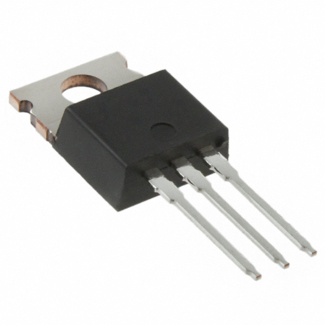
The IRF610 is an N-Channel MOSFET manufactured by Vishay Siliconix, rated for 200V drain-to-source voltage with 3.3A continuous drain current at 25°C. The device is housed in a TO-220AB through-hole package and dissipates up to 36W at the case temperature. The IRF610 is classified as obsolete, which necessitates identification of equivalent and substitute parts for new designs and ongoing production support. Equivalent parts maintain identical electrical and mechanical specifications, while substitute parts offer alternative voltage or current ratings within compatible package configurations.
Substiute Parts
Key Parameters
| Parameter | Value | Unit |
|---|---|---|
| FET Type | N-Channel | — |
| Technology | MOSFET (Metal Oxide) | — |
| Drain to Source Voltage (Vdss) | 200 | V |
| Continuous Drain Current (Id) @ 25°C | 3.3 | A (Tc) |
| Drive Voltage (Max Rds On) | 10 | V |
| Rds On (Max) @ Id, Vgs | 1.5 | Ohm @ 2A, 10V |
| Vgs(th) (Max) @ Id | 4 | V @ 250µA |
| Gate Charge (Qg) (Max) @ Vgs | 8.2 | nC @ 10V |
| Vgs (Max) | ±20 | V |
| Input Capacitance (Ciss) (Max) @ Vds | 140 | pF @ 25V |
| Power Dissipation (Max) | 36 | W (Tc) |
| Operating Temperature | -55 to 150 | °C (TJ) |
| Mounting Type | Through Hole | — |
| Package / Case | TO-220-3 | — |
| Product Status | Obsolete | — |
Substitute Part Grouping Explanation
Substitution of the IRF610 is determined by the following critical parameters: drain-to-source voltage (Vdss), continuous drain current (Id), package type (TO-220-3), and mounting configuration (through-hole). The IRF610 operates at 200V with 3.3A continuous current capability.
Equivalent parts maintain all electrical specifications and package configuration, differing only in product status or packaging format (tube versus bulk). These parts are direct replacements with no circuit redesign required.
Substitute parts are categorized into two groups based on voltage rating:
Group 1: Lower Voltage Substitutes (30V–100V) These parts operate at reduced Vdss ratings (30V, 40V, or 100V) compared to the IRF610 (200V). They are suitable only for applications where the circuit operates below the substitute part's Vdss rating. These substitutes typically offer higher current ratings and lower on-resistance due to lower voltage technology. Substitutes in this group include IPP023N04NGXKSA1 (40V, 90A), IPP041N04NGXKSA1 (40V, 80A), IPP042N03LGXKSA1 (30V, 70A), and IPP12CN10LGXKSA1 (100V, 69A).
Group 2: Higher Voltage Substitute (650V) The IPP60R099CPXKSA1 operates at 650V, exceeding the IRF610 specification. This part is suitable for applications requiring higher voltage blocking capability but operates at reduced current (31A) and higher on-resistance (99mOhm).
All substitute parts maintain the TO-220-3 package configuration and through-hole mounting type. Gate charge, threshold voltage, and maximum gate voltage specifications remain compatible across all listed parts.
Parameter Comparison
| Parameter | IRF610 | IRF610PBF | IRF610PBF-BE3 | IPP023N04NGXKSA1 | IPP041N04NGXKSA1 | IPP042N03LGXKSA1 | IPP12CN10LGXKSA1 | IPP60R099CPXKSA1 |
|---|---|---|---|---|---|---|---|---|
| Manufacturer | Vishay Siliconix | Vishay Siliconix | Vishay Siliconix | Infineon Technologies | Infineon Technologies | Infineon Technologies | Infineon Technologies | Infineon Technologies |
| FET Type | N-Channel | N-Channel | N-Channel | N-Channel | N-Channel | N-Channel | N-Channel | N-Channel |
| Vdss (V) | 200 | 200 | 200 | 40 | 40 | 30 | 100 | 650 |
| Id @ 25°C (A) | 3.3 | 3.3 | 3.3 | 90 | 80 | 70 | 69 | 31 |
| Rds On (Max) @ 10V (Ohm) | 1.5 | 1.5 | 1.5 | 0.0023 | 0.0041 | 0.0042 | 0.012 | 0.099 |
| Vgs(th) (Max) (V) | 4 | 4 | 4 | 4 | 4 | 2.2 | 2.4 | 3.5 |
| Gate Charge (Qg) @ 10V (nC) | 8.2 | 8.2 | 8.2 | 120 | 56 | 38 | 58 | 80 |
| Vgs (Max) (V) | ±20 | ±20 | ±20 | ±20 | ±20 | ±20 | ±20 | ±20 |
| Ciss (Max) @ Vds (pF) | 140 @ 25V | 140 @ 25V | 140 @ 25V | 10000 @ 20V | 4500 @ 20V | 3900 @ 15V | 5600 @ 50V | 2800 @ 100V |
| Power Dissipation (Max) (W) | 36 | 36 | 36 | 167 | 94 | 79 | 125 | 255 |
| Operating Temperature (°C) | -55 to 150 | -55 to 150 | -55 to 150 | -55 to 175 | -55 to 175 | -55 to 175 | -55 to 175 | -55 to 150 |
| Package / Case | TO-220-3 | TO-220-3 | TO-220-3 | TO-220-3 | TO-220-3 | TO-220-3 | TO-220-3 | TO-220-3 |
| Mounting Type | Through Hole | Through Hole | Through Hole | Through Hole | Through Hole | Through Hole | Through Hole | Through Hole |
| Product Status | Obsolete | Active | Active | Active | Active | Not For New Designs | Active | Not For New Designs |
| RoHS Status | Non-compliant | ROHS3 Compliant | ROHS3 Compliant | ROHS3 Compliant | ROHS3 Compliant | ROHS3 Compliant | ROHS3 Compliant | ROHS3 Compliant |
Engineering Selection Recommendations
Direct Equivalents (Recommended for Immediate Replacement)
IRF610PBF and IRF610PBF-BE3 are direct electrical and mechanical equivalents of the IRF610. Both parts maintain identical specifications for Vdss (200V), Id (3.3A), Rds On (1.5 Ohm), and all other electrical parameters. The primary differences are product status and compliance certifications. IRF610PBF is classified as Active and ROHS3 Compliant, making it the preferred choice for new designs and production continuity. IRF610PBF-BE3 is also Active and ROHS3 Compliant. Both parts are available in tube packaging and are suitable for direct socket replacement without circuit modification.
Substitute Selection Based on Application Requirements
Selection of substitute parts requires verification that the application circuit operates within the substitute part's voltage and current specifications.
For applications operating at 40V or below with current requirements up to 90A, IPP023N04NGXKSA1 (40V, 90A, Active status) is suitable. This part offers significantly lower on-resistance (2.3mOhm) and higher current capability than the IRF610.
For applications operating at 40V or below with current requirements up to 80A, IPP041N04NGXKSA1 (40V, 80A, Active status) is suitable. This part provides lower on-resistance (4.1mOhm) and is actively supported.
For applications operating at 100V or below with current requirements up to 69A, IPP12CN10LGXKSA1 (100V, 69A, Active status) is suitable. This part extends voltage capability to 100V while maintaining active product status and ROHS3 compliance.
For applications requiring voltage blocking capability exceeding 200V, IPP60R099CPXKSA1 (650V, 31A) is suitable. This part operates at 650V but is classified as Not For New Designs.
Parts classified as "Not For New Designs" (IPP042N03LGXKSA1 and IPP60R099CPXKSA1) should be avoided for new circuit designs. These parts are suitable only for sustaining existing production or legacy system support.
All substitute parts maintain TO-220-3 package configuration and through-hole mounting, ensuring mechanical compatibility with existing PCB layouts.
Frequently Asked Questions (FAQ)
Q: Can IRF610PBF be used as a direct replacement for IRF610?
A: Yes. IRF610PBF is a direct equivalent with identical electrical specifications (200V, 3.3A, 1.5 Ohm Rds On). The primary advantage is that IRF610PBF is Active and ROHS3 Compliant, whereas IRF610 is Obsolete and RoHS non-compliant. No circuit modification is required.
Q: What is the difference between IRF610PBF and IRF610PBF-BE3?
A: Both parts are electrically and mechanically identical to IRF610. IRF610PBF-BE3 includes a specific binning or test designation (BE3) but maintains the same electrical performance. Both are Active and ROHS3 Compliant. Selection between them depends on supplier availability and internal part numbering requirements.
Q: Can I use IPP023N04NGXKSA1 in place of IRF610?
A: IPP023N04NGXKSA1 can be used only if the application circuit operates at 40V or below. The IRF610 is rated for 200V, while IPP023N04NGXKSA1 is rated for 40V. Using IPP023N04NGXKSA1 in a 200V circuit will result in device failure. However, IPP023N04NGXKSA1 offers superior current handling (90A versus 3.3A) and lower on-resistance (2.3mOhm versus 1.5 Ohm) for low-voltage applications.
Q: Why are some substitute parts marked "Not For New Designs"?
A: Parts marked "Not For New Designs" are in end-of-life or obsolescence phases. Infineon Technologies designates these parts to encourage migration to active alternatives. These parts remain available for sustaining existing production but should not be selected for new circuit designs. IPP042N03LGXKSA1 and IPP60R099CPXKSA1 fall into this category.
Q: Are all substitute parts available in TO-220-3 package?
A: Yes. All substitute parts listed maintain the TO-220-3 package configuration and through-hole mounting type, ensuring mechanical compatibility with existing PCB layouts and thermal management solutions.
Q: What is the significance of gate charge (Qg) differences between IRF610 and substitute parts?
A: Gate charge affects switching speed and driver circuit requirements. IRF610 has 8.2 nC gate charge, while substitute parts range from 38 nC to 120 nC. Higher gate charge requires more driver current and increases switching losses. For direct replacement (IRF610PBF or IRF610PBF-BE3), gate charge remains identical at 8.2 nC. For voltage-rated substitutes, gate charge differences must be evaluated against driver circuit capabilities.
Q: Can I use IPP12CN10LGXKSA1 as a substitute for IRF610?
A: IPP12CN10LGXKSA1 can be used if the application circuit operates at 100V or below. The IRF610 is rated for 200V, while IPP12CN10LGXKSA1 is rated for 100V. IPP12CN10LGXKSA1 offers higher current capability (69A versus 3.3A) and is classified as Active with ROHS3 compliance, making it suitable for low-voltage applications requiring higher current handling.
Q: What compliance certifications should I verify when selecting a substitute?
A: Verify RoHS status and REACH compliance based on your application requirements. All listed substitute parts are ROHS3 Compliant. IRF610 is RoHS non-compliant, while IRF610PBF and IRF610PBF-BE3 are ROHS3 Compliant. For applications subject to RoHS regulations, direct equivalents (IRF610PBF or IRF610PBF-BE3) are required.
Q: How do I determine if a lower-voltage substitute is suitable for my application?
A: Review the circuit schematic to identify the maximum voltage that will appear across the drain-to-source terminals under all operating conditions, including transient overvoltages. The substitute part's Vdss rating must exceed this maximum voltage with adequate safety margin. If the maximum circuit voltage is 40V, IPP023N04NGXKSA1 or IPP041N04NGXKSA1 are suitable. If the maximum circuit voltage is 100V, IPP12CN10LGXKSA1 is suitable. If the maximum circuit voltage exceeds 100V but is below 200V, only IRF610PBF or IRF610PBF-BE3 are suitable.
Alternative Parts

SJ6012L2TP
Littelfuse Inc.
6 Alternative Parts

JMK107BBJ476MA-RE
Taiyo Yuden
10 Alternative Parts

GMK107BBJ475MA-T
Taiyo Yuden
5 Alternative Parts
SJ6020N2ARP
Littelfuse Inc.
3 Alternative Parts
SJ6025R2ATP
Littelfuse Inc.
4 Alternative Parts

2474-05L
API Delevan Inc.
1 Alternative Parts

4590R-684K
API Delevan Inc.
1 Alternative Parts

CM6560R-334
API Delevan Inc.
1 Alternative Parts

CM6460-104
API Delevan Inc.
1 Alternative Parts

5526-12
API Delevan Inc.
1 Alternative Parts