


Request Quote
(Ships tomorrow)
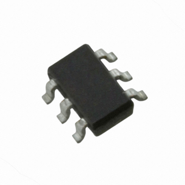
IRF5851 MOSFET N/P-Channel Equivalent & Substitute Parts
Part Overview
The IRF5851 is an Infineon Technologies HEXFET® N and P-channel MOSFET array designed for surface mount applications in 6-TSOP packaging. This dual-channel device operates at 20V drain-to-source voltage with continuous drain currents of 2.7A (N-channel) and 2.2A (P-channel), delivering 960mW maximum power dissipation. The IRF5851 is classified as obsolete product status, making equivalent and substitute parts necessary for ongoing design support, production continuity, and component sourcing in applications requiring logic-level gate drive MOSFET arrays.
Substiute Parts
Key Parameters
| Parameter | Value | Specification |
|---|---|---|
| Manufacturer Part Number | IRF5851 | Infineon Technologies |
| Configuration | N and P-Channel | Dual-channel MOSFET array |
| Drain-to-Source Voltage (Vdss) | 20V | Maximum rated voltage |
| Continuous Drain Current (Id) @ 25°C | 2.7A, 2.2A | N-channel, P-channel respectively |
| On-Resistance (Rds On) | 90mOhm @ 2.7A, 4.5V | Maximum at specified conditions |
| Gate Threshold Voltage (Vgs(th)) | 1.25V @ 250µA | Logic level gate |
| Gate Charge (Qg) | 6nC @ 4.5V | Maximum |
| Input Capacitance (Ciss) | 400pF @ 15V | Maximum |
| Power Dissipation | 960mW | Maximum |
| Package Type | SOT-23-6 Thin / TSOT-23-6 | Surface mount |
| Product Status | Obsolete | No longer in production |
| RoHS Compliance | Non-compliant | RoHS status |
Substitute Part Grouping Explanation
Substitute parts for the IRF5851 are qualified based on the following electrical and mechanical parameters:
Primary Substitution Criteria:
- Configuration: N and P-channel dual MOSFET array
- Drain-to-Source Voltage (Vdss): 20V or higher
- Continuous Drain Current (Id): 2.7A or higher for N-channel; 2.2A or higher for P-channel
- Gate Feature: Logic level gate drive capability
- Package Type: SOT-23-6 Thin or TSOT-23-6 surface mount
- Mounting Type: Surface mount
Secondary Compatibility Parameters:
- On-Resistance (Rds On): Lower or equivalent values preferred
- Gate Charge (Qg): Lower or equivalent values preferred
- Input Capacitance (Ciss): Lower or equivalent values preferred
- Power Dissipation: 700mW or higher acceptable
- Operating Temperature Range: -55°C to 150°C (TJ)
The substitute parts FDC6327C and FDC6333C from onsemi meet these criteria with active product status and RoHS3 compliance, providing improved availability and regulatory compliance compared to the obsolete IRF5851.
Parameter Comparison
| Parameter | IRF5851 (Infineon) | FDC6327C (onsemi) | FDC6333C (onsemi) |
|---|---|---|---|
| Manufacturer | Infineon Technologies | onsemi | onsemi |
| Configuration | N and P-Channel | N and P-Channel | N and P-Channel |
| Drain-to-Source Voltage (Vdss) | 20V | 20V | 30V |
| Continuous Drain Current (Id) @ 25°C | 2.7A, 2.2A | 2.7A, 1.9A | 2.5A, 2.0A |
| On-Resistance (Rds On) | 90mOhm @ 2.7A, 4.5V | 80mOhm @ 2.7A, 4.5V | 95mOhm @ 2.5A, 10V |
| Gate Threshold Voltage (Vgs(th)) | 1.25V @ 250µA | 1.5V @ 250µA | 3V @ 250µA |
| Gate Charge (Qg) | 6nC @ 4.5V | 4.5nC @ 4.5V | 6.6nC @ 10V |
| Input Capacitance (Ciss) | 400pF @ 15V | 325pF @ 10V | 282pF @ 15V |
| Power Dissipation (Max) | 960mW | 700mW | 700mW |
| Package Type | SOT-23-6 Thin / TSOT-23-6 | SOT-23-6 Thin / TSOT-23-6 | SOT-23-6 Thin / TSOT-23-6 |
| Product Status | Obsolete | Active | Active |
| RoHS Compliance | Non-compliant | RoHS3 Compliant | RoHS3 Compliant |
| Operating Temperature | Not specified | -55°C ~ 150°C (TJ) | -55°C ~ 150°C (TJ) |
Engineering Selection Recommendations
FDC6327C Selection Criteria:
The FDC6327C is the primary substitute for IRF5851 applications requiring direct voltage and current compatibility. This onsemi PowerTrench® device maintains the 20V Vdss rating and 2.7A N-channel continuous drain current specification. The FDC6327C offers improved on-resistance (80mOhm versus 90mOhm), lower gate charge (4.5nC versus 6nC), and reduced input capacitance (325pF versus 400pF), resulting in enhanced switching efficiency. Active product status ensures long-term availability and supply chain continuity. RoHS3 compliance satisfies modern regulatory requirements. The 700mW power dissipation rating is acceptable for applications where the IRF5851's 960mW rating was not fully utilized.
FDC6333C Selection Criteria:
The FDC6333C is suitable for applications where higher voltage margin is beneficial. This device provides 30V Vdss rating, offering 50% additional voltage headroom compared to the IRF5851. Continuous drain currents of 2.5A (N-channel) and 2.0A (P-channel) meet or exceed IRF5851 specifications. The FDC6333C exhibits lower input capacitance (282pF) and reduced gate charge characteristics. Active product status and RoHS3 compliance provide regulatory and supply assurance. Selection of FDC6333C is appropriate for designs requiring enhanced voltage margin or where component standardization across multiple voltage ratings is desired.
Compliance and Availability:
Both substitute parts are active products with RoHS3 compliance, addressing the obsolete status and non-compliance issues of the IRF5851. Inventory availability for FDC6327C (98,300 pcs) and FDC6333C (57,831 pcs) supports production requirements. Both devices are supplied in identical SOT-23-6 Thin packaging, enabling direct board-level substitution without layout modifications.
Frequently Asked Questions (FAQ)
Q: Can FDC6327C directly replace IRF5851 in existing designs?
A: Yes. The FDC6327C maintains identical 20V Vdss and 2.7A N-channel current ratings, operates with logic-level gate drive, and uses the same SOT-23-6 Thin package. Electrical performance is equivalent or superior across all specified parameters. No circuit modifications are required.
Q: What is the difference between FDC6327C and FDC6333C?
A: The primary difference is Vdss rating: FDC6327C operates at 20V (matching IRF5851), while FDC6333C operates at 30V. The FDC6333C provides higher voltage margin but with slightly different gate threshold voltage (3V versus 1.5V). Selection depends on application voltage requirements and gate drive circuit design.
Q: Are both substitute parts RoHS compliant?
A: Yes. Both FDC6327C and FDC6333C are RoHS3 compliant, addressing the non-compliance status of the obsolete IRF5851. This compliance is mandatory for applications subject to RoHS regulations.
Q: Will the lower power dissipation rating of substitute parts affect my design?
A: The FDC6327C and FDC6333C are rated at 700mW versus IRF5851's 960mW. If your application required the full 960mW rating, thermal analysis is necessary. However, the improved on-resistance and lower gate charge of substitute parts typically result in lower actual power dissipation during operation, often compensating for the lower rated maximum.
Q: Are there any gate drive circuit modifications needed?
A: No modifications are required. Both substitute parts feature logic-level gate drive capability with Vgs(th) specifications compatible with standard 3.3V and 5V logic circuits. Gate charge values are lower than IRF5851, potentially improving switching speed.
Q: What is the package compatibility?
A: All three devices use SOT-23-6 Thin (TSOT-23-6) surface mount packaging. Pin assignments and footprints are identical, enabling direct PCB substitution without layout changes.
Q: Which substitute part should I select for new designs?
A: For new designs, FDC6327C is recommended as the primary choice due to exact voltage rating match with IRF5851 and active product status. FDC6333C is appropriate if higher voltage margin is a design requirement or for standardization across multiple voltage-rated applications.
Alternative Parts

SJ6012L2TP
Littelfuse Inc.
6 Alternative Parts

JMK107BBJ476MA-RE
Taiyo Yuden
10 Alternative Parts

GMK107BBJ475MA-T
Taiyo Yuden
5 Alternative Parts
SJ6020N2ARP
Littelfuse Inc.
3 Alternative Parts
SJ6025R2ATP
Littelfuse Inc.
4 Alternative Parts

2474-05L
API Delevan Inc.
1 Alternative Parts

4590R-684K
API Delevan Inc.
1 Alternative Parts

CM6560R-334
API Delevan Inc.
1 Alternative Parts

CM6460-104
API Delevan Inc.
1 Alternative Parts

5526-12
API Delevan Inc.
1 Alternative Parts