


Request Quote
(Ships tomorrow)
IRF5805TR P-Channel MOSFET Equivalent & Substitute Parts
Part Overview
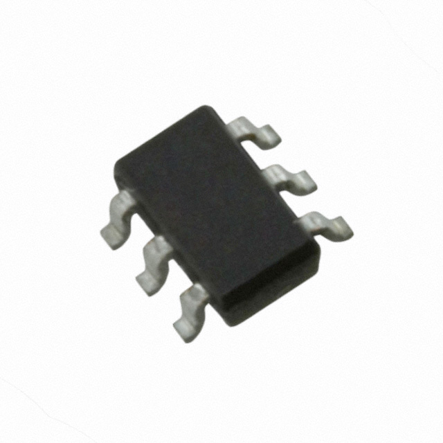
The IRF5805TR is a P-Channel MOSFET manufactured by Infineon Technologies, rated for 30V drain-to-source voltage with 3.8A continuous drain current at 25°C. The device is packaged in a Micro6™ (TSOP-6) surface mount configuration and is part of the HEXFET® series. This part is classified as obsolete, making identification of equivalent and substitute components necessary for ongoing design support and production continuity. Substitute parts must maintain compatibility across electrical ratings, thermal characteristics, and mechanical packaging to ensure direct replacement capability.
Substiute Parts
Key Parameters
| Parameter | Value | Unit |
|---|---|---|
| FET Type | P-Channel | — |
| Drain to Source Voltage (Vdss) | 30 | V |
| Current - Continuous Drain (Id) @ 25°C | 3.8 | A |
| Rds On (Max) @ Id, Vgs | 98 | mOhm @ 3.8A, 10V |
| Gate Charge (Qg) (Max) @ Vgs | 17 | nC @ 10V |
| Power Dissipation (Max) | 2 | W |
| Operating Temperature Range | -55 to 150 | °C (TJ) |
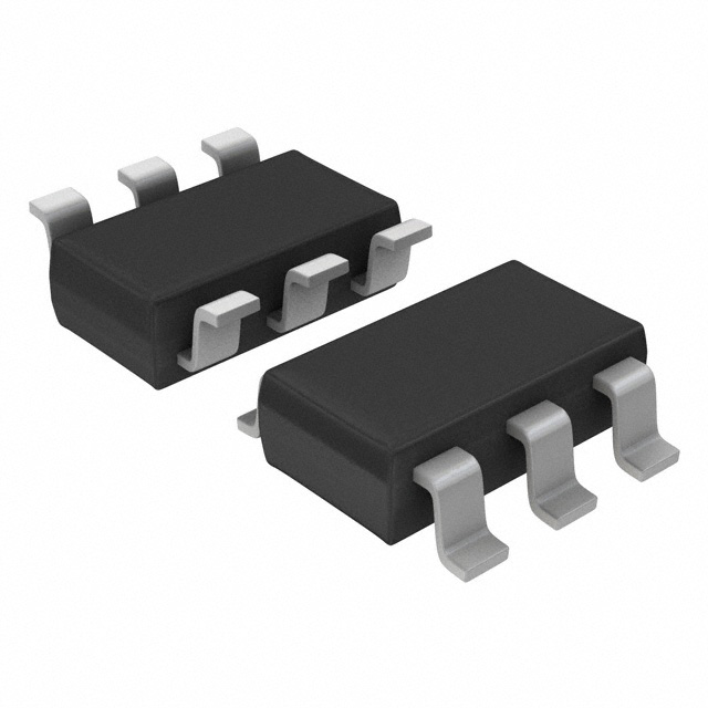
| Package / Case | SOT-23-6 Thin, TSOT-23-6 | — |
| Mounting Type | Surface Mount | — |
Substitute Part Grouping Explanation
Substitution of the IRF5805TR is determined by strict adherence to the following electrical and mechanical parameters:
Primary Substitution Criteria:
- FET Type: P-Channel (required match)
- Drain to Source Voltage (Vdss): 30V (required match)
- Package / Case: SOT-23-6 Thin, TSOT-23-6 (required match for mechanical compatibility)
- Mounting Type: Surface Mount (required match)
- Operating Temperature Range: -55°C to 150°C (required match)
Secondary Compatibility Parameters:
- Continuous Drain Current (Id) @ 25°C: minimum 3.8A
- Rds On (Max) @ 10V: maximum 98 mOhm
- Gate Charge (Qg) @ 10V: maximum 17 nC
- Power Dissipation (Max): minimum 2W
The substitute parts FDC654P and NTGS4111PT1G meet the primary substitution criteria. Both are P-Channel MOSFETs rated for 30V Vdss, packaged in SOT-23-6 surface mount configurations, and rated for the same operating temperature range. Variations in secondary parameters (drain current, Rds On, gate charge, and power dissipation) are within acceptable engineering tolerances for direct replacement applications.
Parameter Comparison
| Parameter | IRF5805TR (Main) | FDC654P (Substitute) | NTGS4111PT1G (Substitute) |
|---|---|---|---|
| Manufacturer | Infineon Technologies | Fairchild Semiconductor | onsemi |
| FET Type | P-Channel | P-Channel | P-Channel |
| Drain to Source Voltage (Vdss) | 30 V | 30 V | 30 V |
| Current - Continuous Drain (Id) @ 25°C | 3.8 A | 3.6 A | 2.6 A |
| Rds On (Max) @ Id, Vgs | 98 mOhm @ 3.8A, 10V | 75 mOhm @ 3.6A, 10V | 60 mOhm @ 3.7A, 10V |
| Gate Charge (Qg) (Max) @ Vgs | 17 nC @ 10V | 9 nC @ 10V | 32 nC @ 10V |
| Power Dissipation (Max) | 2 W | 1.6 W | 630 mW |
| Operating Temperature Range | -55 to 150 °C (TJ) | -55 to 150 °C (TJ) | -55 to 150 °C (TJ) |
| Package / Case | SOT-23-6 Thin, TSOT-23-6 | SOT-23-6 Thin, TSOT-23-6 | SOT-23-6 Thin, TSOT-23-6 |
| Mounting Type | Surface Mount | Surface Mount | Surface Mount |
| Product Status | Obsolete | Active | Active |
Engineering Selection Recommendations
FDC654P (Fairchild Semiconductor): The FDC654P is an active product with electrical characteristics closely aligned to the IRF5805TR. It provides lower on-resistance (75 mOhm versus 98 mOhm) and reduced gate charge (9 nC versus 17 nC), resulting in improved switching efficiency. Power dissipation is rated at 1.6W, which is lower than the main part's 2W rating. The FDC654P is suitable for applications where the IRF5805TR's performance envelope is acceptable and where lower power dissipation is beneficial. This part is not listed with RoHS compliance status in the provided data.
NTGS4111PT1G (onsemi): The NTGS4111PT1G is an active product with the lowest on-resistance (60 mOhm) and lowest power dissipation (630 mW) among the three options. However, it has a lower continuous drain current rating (2.6A versus 3.8A) and higher gate charge (32 nC versus 17 nC). The NTGS4111PT1G is ROHS3 compliant and available in Cut Tape and Digi-Reel® packaging formats. This part is suitable for applications where the 2.6A current rating is sufficient and where RoHS compliance is required. The higher gate charge may result in increased switching losses in high-frequency applications.
Selection Basis:
- Both substitute parts are active products, ensuring long-term availability and supply chain stability.
- Both maintain the required 30V Vdss rating and SOT-23-6 package compatibility.
- FDC654P is recommended for applications requiring performance closest to the IRF5805TR with improved efficiency.
- NTGS4111PT1G is recommended for applications requiring RoHS compliance and where the 2.6A current rating is adequate.
Frequently Asked Questions (FAQ)
Q: Can the FDC654P or NTGS4111PT1G be used as direct replacements for the IRF5805TR on existing PCBs?
A: Yes, both substitute parts are compatible with existing PCB layouts designed for the IRF5805TR. All three devices use the SOT-23-6 surface mount package with identical pin configurations and mechanical dimensions. No PCB modifications are required.
Q: What is the significance of the lower drain current rating in the NTGS4111PT1G (2.6A versus 3.8A)?
A: The NTGS4111PT1G has a lower continuous drain current specification. Applications requiring sustained currents above 2.6A must use either the IRF5805TR or FDC654P. For applications operating below 2.6A, the NTGS4111PT1G is fully compatible.
Q: How do the on-resistance differences affect circuit performance?
A: On-resistance (Rds On) directly impacts power dissipation and heat generation. The FDC654P (75 mOhm) and NTGS4111PT1G (60 mOhm) have lower on-resistance than the IRF5805TR (98 mOhm), resulting in reduced power loss and lower junction temperatures under the same operating conditions. This can improve overall circuit efficiency and reliability.
Q: What is the impact of gate charge differences on switching speed?
A: Gate charge (Qg) affects the time required to switch the transistor on and off. The FDC654P has lower gate charge (9 nC) compared to the IRF5805TR (17 nC), enabling faster switching transitions. The NTGS4111PT1G has higher gate charge (32 nC), which may increase switching losses in high-frequency applications. For low-frequency switching applications, gate charge differences are negligible.
Q: Are there compliance or certification differences between the substitute parts?
A: The IRF5805TR is RoHS non-compliant. The FDC654P compliance status is not specified in the provided data. The NTGS4111PT1G is ROHS3 compliant. For applications requiring RoHS compliance, the NTGS4111PT1G is the appropriate selection. All three parts are REACH unaffected and classified as EAR99 for export control purposes.
Q: What packaging options are available for the substitute parts?
A: The IRF5805TR is supplied in standard surface mount format. The FDC654P is supplied in standard surface mount format. The NTGS4111PT1G is available in Cut Tape (CT) and Digi-Reel® packaging formats, providing flexibility for both manual and automated assembly processes.
Q: Can the substitute parts handle the same power dissipation as the IRF5805TR?
A: The FDC654P is rated for 1.6W maximum power dissipation, which is lower than the IRF5805TR's 2W rating. The NTGS4111PT1G is rated for 630 mW, which is significantly lower. For applications requiring sustained power dissipation near 2W, the FDC654P is the more suitable substitute. For lower power applications, the NTGS4111PT1G is adequate.
Alternative Parts

SJ6012L2TP
Littelfuse Inc.
6 Alternative Parts

JMK107BBJ476MA-RE
Taiyo Yuden
10 Alternative Parts

GMK107BBJ475MA-T
Taiyo Yuden
5 Alternative Parts
SJ6020N2ARP
Littelfuse Inc.
3 Alternative Parts
SJ6025R2ATP
Littelfuse Inc.
4 Alternative Parts

2474-05L
API Delevan Inc.
1 Alternative Parts

4590R-684K
API Delevan Inc.
1 Alternative Parts

CM6560R-334
API Delevan Inc.
1 Alternative Parts

CM6460-104
API Delevan Inc.
1 Alternative Parts

5526-12
API Delevan Inc.
1 Alternative Parts