


Request Quote
(Ships tomorrow)
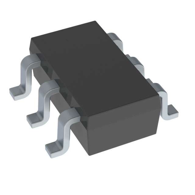
IRF5804TRPBF P-Channel MOSFET Equivalent & Substitute Parts
Part Overview
The IRF5804TRPBF is a P-Channel MOSFET manufactured by Infineon Technologies, rated for 40V drain-to-source voltage with 2.5A continuous drain current at 25°C. This device is packaged in a Micro6™ (TSOP-6) surface mount configuration and is designed for applications requiring P-channel switching and amplification in compact form factors.
The IRF5804TRPBF carries an Obsolete product status. Locating equivalent substitute components is necessary to maintain design continuity, ensure supply chain availability, and support ongoing production requirements for legacy systems or redesign initiatives.
Substiute Parts
Key Parameters
| Parameter | Value | Unit |
|---|---|---|
| FET Type | P-Channel | — |
| Drain to Source Voltage (Vdss) | 40 | V |
| Current - Continuous Drain (Id) @ 25°C | 2.5 | A (Ta) |
| Rds On (Max) @ Id, Vgs | 198 | mOhm @ 2.5A, 10V |
| Vgs(th) (Max) @ Id | 3 | V @ 250µA |
| Gate Charge (Qg) (Max) @ Vgs | 8.5 | nC @ 10V |
| Power Dissipation (Max) | 2 | W (Ta) |
| Operating Temperature Range | -55 to 150 | °C (TJ) |
| Package / Case | SOT-23-6 Thin, TSOT-23-6 | — |
| Mounting Type | Surface Mount | — |
Substitute Part Grouping Explanation
Substitution of the IRF5804TRPBF requires evaluation against the following critical parameters:
Voltage Rating: The substitute must support a minimum Vdss of 40V to ensure equivalent or superior voltage handling capability.
Current Rating: The substitute must support continuous drain current (Id) at or above 2.5A at 25°C to maintain functional equivalence in switching and amplification applications.
On-State Resistance (Rds On): The substitute's maximum on-state resistance must not exceed the specified 198 mOhm @ 2.5A, 10V to ensure comparable power dissipation and thermal performance.
Gate Threshold Voltage (Vgs(th)): The substitute must maintain a maximum gate threshold voltage of 3V @ 250µA to ensure compatible gate drive requirements.
Power Dissipation: The substitute must support a minimum power dissipation rating of 2W (Ta) to handle equivalent thermal loads.
Package Compatibility: The substitute must be housed in a SOT-23-6 Thin or TSOT-23-6 package to ensure mechanical and electrical compatibility with existing PCB layouts.
Operating Temperature Range: The substitute must support the full operating temperature range of -55°C to 150°C (TJ).
The SI3438DV-T1-GE3 is identified as a substitute based on matching voltage rating, package type, gate threshold voltage, and operating temperature range. However, the SI3438DV-T1-GE3 is an N-Channel device, which represents a functional topology change and requires circuit redesign considerations.
Parameter Comparison
| Parameter | IRF5804TRPBF | SI3438DV-T1-GE3 | Unit |
|---|---|---|---|
| Manufacturer | Infineon Technologies | Vishay Siliconix | — |
| FET Type | P-Channel | N-Channel | — |
| Drain to Source Voltage (Vdss) | 40 | 40 | V |
| Current - Continuous Drain (Id) @ 25°C | 2.5 (Ta) | 7.4 (Tc) | A |
| Rds On (Max) @ Id, Vgs | 198 @ 2.5A, 10V | 35.5 @ 5A, 10V | mOhm |
| Vgs(th) (Max) @ Id | 3 @ 250µA | 3 @ 250µA | V |
| Gate Charge (Qg) (Max) @ Vgs | 8.5 @ 10V | 20 @ 10V | nC |
| Vgs (Max) | ±20 | ±20 | V |
| Input Capacitance (Ciss) (Max) @ Vds | 680 @ 25V | 640 @ 20V | pF |
| Power Dissipation (Max) | 2 (Ta) | 2 (Ta), 3.5 (Tc) | W |
| Operating Temperature Range | -55 to 150 | -55 to 150 | °C (TJ) |
| Package / Case | SOT-23-6 Thin, TSOT-23-6 | SOT-23-6 Thin, TSOT-23-6 | — |
| Mounting Type | Surface Mount | Surface Mount | — |
| Product Status | Obsolete | Active | — |
| RoHS Status | — | ROHS3 Compliant | — |
| Moisture Sensitivity Level (MSL) | 2 (1 Year) | 1 (Unlimited) | — |
Engineering Selection Recommendations
Product Status Consideration: The IRF5804TRPBF is classified as Obsolete. The SI3438DV-T1-GE3 carries Active product status, indicating ongoing manufacturer support, availability, and compliance with current industry standards.
Compliance and Certifications: The SI3438DV-T1-GE3 is ROHS3 Compliant, whereas compliance information for the IRF5804TRPBF is not provided in the available data. Both devices are REACH Unaffected and carry EAR99 ECCN classification.
Moisture Sensitivity: The SI3438DV-T1-GE3 has MSL 1 (Unlimited shelf life), compared to the IRF5804TRPBF MSL 2 (1 Year shelf life). This provides superior long-term storage and handling characteristics for the substitute.
Channel Type Difference: The SI3438DV-T1-GE3 is an N-Channel device, whereas the IRF5804TRPBF is P-Channel. This fundamental difference requires circuit topology evaluation and potential redesign of gate drive and switching logic. Direct pin-for-pin substitution is not possible without circuit modification.
Electrical Performance: The SI3438DV-T1-GE3 demonstrates superior on-state resistance (35.5 mOhm @ 5A, 10V) compared to the IRF5804TRPBF (198 mOhm @ 2.5A, 10V), resulting in lower conduction losses. The SI3438DV-T1-GE3 also supports higher continuous drain current (7.4A Tc versus 2.5A Ta), providing design margin for thermal and current handling.
Gate Charge: The SI3438DV-T1-GE3 exhibits higher gate charge (20 nC @ 10V) compared to the IRF5804TRPBF (8.5 nC @ 10V), requiring evaluation of gate drive circuit capability and switching speed requirements.
Frequently Asked Questions (FAQ)
Q: Can the SI3438DV-T1-GE3 be used as a direct pin-for-pin replacement for the IRF5804TRPBF?
A: No. While both devices share the SOT-23-6 package and identical pin count, the SI3438DV-T1-GE3 is N-Channel and the IRF5804TRPBF is P-Channel. These represent opposite polarity devices with different gate drive requirements and switching logic. Circuit redesign is required for substitution.
Q: What are the key electrical differences between these devices?
A: The SI3438DV-T1-GE3 provides higher continuous drain current (7.4A Tc versus 2.5A Ta), significantly lower on-state resistance (35.5 mOhm versus 198 mOhm), and higher gate charge (20 nC versus 8.5 nC). These differences result in improved power efficiency but require gate drive circuit evaluation.
Q: Are the package dimensions identical between IRF5804TRPBF and SI3438DV-T1-GE3?
A: Both devices are specified as SOT-23-6 Thin and TSOT-23-6 packages. Mechanical compatibility with existing PCB layouts is supported. Verification of exact footprint dimensions with manufacturer datasheets is recommended for final design validation.
Q: What is the significance of the MSL rating difference?
A: The IRF5804TRPBF has MSL 2 (1 Year shelf life), while the SI3438DV-T1-GE3 has MSL 1 (Unlimited shelf life). MSL 1 provides superior moisture resistance and longer storage capability without baking requirements, reducing handling and storage costs.
Q: Does the SI3438DV-T1-GE3 meet current compliance standards?
A: Yes. The SI3438DV-T1-GE3 is ROHS3 Compliant and REACH Unaffected. The IRF5804TRPBF, being Obsolete, may not meet current regulatory requirements for new designs or production.
Q: How do the gate threshold voltages compare?
A: Both devices specify identical maximum gate threshold voltage of 3V @ 250µA, ensuring compatible gate drive voltage requirements at the threshold level.
Q: What thermal performance differences exist?
A: The SI3438DV-T1-GE3 supports 2W (Ta) and 3.5W (Tc) power dissipation, compared to the IRF5804TRPBF at 2W (Ta). The SI3438DV-T1-GE3 provides additional thermal capacity when measured at case temperature (Tc), supporting higher power applications.
Alternative Parts

SJ6012L2TP
Littelfuse Inc.
6 Alternative Parts

JMK107BBJ476MA-RE
Taiyo Yuden
10 Alternative Parts

GMK107BBJ475MA-T
Taiyo Yuden
5 Alternative Parts
SJ6020N2ARP
Littelfuse Inc.
3 Alternative Parts
SJ6025R2ATP
Littelfuse Inc.
4 Alternative Parts

2474-05L
API Delevan Inc.
1 Alternative Parts

4590R-684K
API Delevan Inc.
1 Alternative Parts

CM6560R-334
API Delevan Inc.
1 Alternative Parts

CM6460-104
API Delevan Inc.
1 Alternative Parts

5526-12
API Delevan Inc.
1 Alternative Parts