


Request Quote
(Ships tomorrow)
IRF5802 Equivalent & Substitute Parts Reference
Part Overview
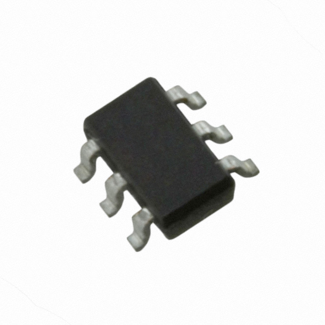
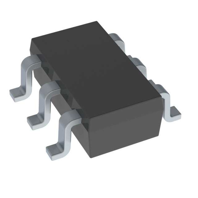
The IRF5802 is an N-Channel MOSFET manufactured by Infineon Technologies, designed for surface mount applications in the Micro6™ (TSOP-6) package. This device features a 150V drain-to-source voltage rating with 900mA continuous drain current capability and 2W power dissipation at ambient temperature. The IRF5802 is classified as obsolete product status, making identification of functionally equivalent alternatives necessary for ongoing design support and component procurement.
Substiute Parts
Key Parameters
| Parameter | Value | Condition |
|---|---|---|
| Drain to Source Voltage (Vdss) | 150 V | — |
| Continuous Drain Current (Id) | 900 mA | @ 25°C (Ta) |
| On-State Resistance (Rds On Max) | 1.2 Ω | @ 540mA, 10V Vgs |
| Gate Threshold Voltage (Vgs th Max) | 5.5 V | @ 250µA |
| Gate Charge (Qg Max) | 6.8 nC | @ 10V Vgs |
| Input Capacitance (Ciss Max) | 88 pF | @ 25V Vds |
| Power Dissipation (Max) | 2 W | @ Ta |
| Package Type | SOT-23-6 Thin (TSOP-6) | Surface Mount |
| Product Status | Obsolete | — |
Substitute Part Grouping Explanation
Substitution of the IRF5802 requires evaluation based on the following critical parameters:
Package Compatibility: The IRF5802 uses SOT-23-6 Thin (TSOP-6) surface mount packaging. Substitute parts must use identical or mechanically compatible package types to ensure PCB layout compatibility without redesign.
Voltage Rating: The 150V Vdss rating establishes the maximum drain-to-source voltage the device can withstand. Substitute parts must maintain equal or higher voltage ratings to ensure safe operation in the original application circuit.
Current Handling: The 900mA continuous drain current at 25°C defines the minimum current capability required. Substitute parts must support equal or greater current ratings under specified conditions.
On-State Resistance: The 1.2Ω Rds On (Max) specification at 540mA and 10V Vgs determines power dissipation and thermal performance. Lower Rds On values improve efficiency; higher values may require thermal management reassessment.
Gate Drive Characteristics: The 5.5V gate threshold voltage and 6.8nC gate charge define the gate drive requirements. Substitute parts with significantly different gate characteristics may require driver circuit modifications.
Thermal Performance: The 2W power dissipation rating at ambient temperature establishes thermal design constraints. Substitute parts must support equivalent or superior thermal performance.
Compliance Status: The IRF5802 is RoHS non-compliant. Modern substitute parts typically carry RoHS3 compliance, reflecting current regulatory requirements.
Parameter Comparison
| Parameter | IRF5802 (Main Part) | SI3442BDV-T1-E3 (Substitute) | Compatibility Notes |
|---|---|---|---|
| Manufacturer | Infineon Technologies | Vishay Siliconix | Different manufacturer |
| FET Type | N-Channel | N-Channel | Matched |
| Drain to Source Voltage (Vdss) | 150 V | 20 V | Substitute rated lower; suitable only for applications operating below 20V |
| Continuous Drain Current (Id) | 900 mA | 3 A | Substitute exceeds requirement |
| On-State Resistance (Rds On Max) | 1.2 Ω @ 540mA, 10V | 57 mΩ @ 4A, 4.5V | Substitute significantly lower; improved efficiency |
| Gate Threshold Voltage (Vgs th Max) | 5.5 V @ 250µA | 1.8 V @ 250µA | Substitute lower; different gate drive requirements |
| Gate Charge (Qg Max) | 6.8 nC @ 10V | 5 nC @ 4.5V | Substitute lower; reduced gate drive power |
| Input Capacitance (Ciss Max) | 88 pF @ 25V | 295 pF @ 10V | Substitute higher; may affect switching speed |
| Power Dissipation (Max) | 2 W | 860 mW | Substitute lower; reduced thermal load |
| Package Type | SOT-23-6 Thin (TSOP-6) | SOT-23-6 Thin (TSOP-6) | Matched |
| Product Status | Obsolete | Active | Substitute actively manufactured |
| RoHS Status | RoHS non-compliant | RoHS3 Compliant | Substitute meets current compliance requirements |
| Moisture Sensitivity Level (MSL) | 1 (Unlimited) | 1 (Unlimited) | Matched |
Engineering Selection Recommendations
Voltage Rating Limitation: The SI3442BDV-T1-E3 carries a 20V Vdss rating, which is substantially lower than the IRF5802's 150V rating. This substitute is suitable only for applications where the actual operating drain-to-source voltage does not exceed 20V. Applications requiring the full 150V capability of the IRF5802 cannot use this substitute without circuit redesign to reduce voltage stress.
Current and Thermal Performance: The SI3442BDV-T1-E3 provides superior current handling (3A versus 900mA) and lower on-state resistance (57mΩ versus 1.2Ω), resulting in reduced power dissipation (860mW versus 2W). These characteristics make the substitute suitable for applications where thermal management is a design constraint.
Gate Drive Compatibility: The SI3442BDV-T1-E3 exhibits a lower gate threshold voltage (1.8V versus 5.5V) and lower gate charge (5nC versus 6.8nC). Gate driver circuits designed for the IRF5802 may require adjustment to accommodate these differences, particularly in low-voltage gate drive applications.
Compliance and Availability: The SI3442BDV-T1-E3 is actively manufactured with RoHS3 compliance, addressing regulatory requirements for new designs. The IRF5802's obsolete status and RoHS non-compliance status make the substitute preferable for new product development and long-term supply chain stability.
Package Compatibility: Both devices use identical SOT-23-6 Thin (TSOP-6) surface mount packaging, eliminating PCB layout redesign requirements from a mechanical standpoint.
Frequently Asked Questions (FAQ)
Q: Can the SI3442BDV-T1-E3 directly replace the IRF5802 in all applications?
A: No. The SI3442BDV-T1-E3 has a 20V Vdss rating compared to the IRF5802's 150V rating. Direct substitution is limited to applications where the drain-to-source voltage remains below 20V. Applications requiring higher voltage operation require alternative parts or circuit redesign.
Q: What are the gate drive differences between these two devices?
A: The SI3442BDV-T1-E3 has a lower gate threshold voltage (1.8V versus 5.5V) and lower gate charge (5nC versus 6.8nC). Gate driver circuits may require adjustment to ensure proper switching performance, particularly in applications using low-voltage gate drive signals.
Q: Are the packages mechanically identical?
A: Yes. Both the IRF5802 and SI3442BDV-T1-E3 use SOT-23-6 Thin (TSOP-6) surface mount packaging. PCB footprints and land patterns are compatible without modification.
Q: What is the significance of the RoHS compliance difference?
A: The IRF5802 is RoHS non-compliant, while the SI3442BDV-T1-E3 is RoHS3 compliant. For new product designs and applications subject to RoHS regulations, the SI3442BDV-T1-E3 meets current compliance requirements. The IRF5802 may be restricted in certain markets or applications.
Q: How do the on-state resistance values affect circuit performance?
A: The SI3442BDV-T1-E3's lower on-state resistance (57mΩ versus 1.2Ω) results in lower power dissipation and reduced heat generation. This improves efficiency but may require circuit analysis to confirm thermal performance meets application requirements.
Q: Is the SI3442BDV-T1-E3 suitable for high-voltage switching applications?
A: No. The 20V Vdss rating limits the SI3442BDV-T1-E3 to low-voltage applications. High-voltage switching applications requiring 150V operation must use alternative parts with appropriate voltage ratings.
Q: What inventory status should be considered for procurement?
A: The IRF5802 has 1435 pieces in stock but is obsolete, indicating limited future availability. The SI3442BDV-T1-E3 has 18208 pieces in stock and active product status, ensuring long-term supply chain availability for new designs.
Alternative Parts

SJ6012L2TP
Littelfuse Inc.
6 Alternative Parts

JMK107BBJ476MA-RE
Taiyo Yuden
10 Alternative Parts

GMK107BBJ475MA-T
Taiyo Yuden
5 Alternative Parts
SJ6020N2ARP
Littelfuse Inc.
3 Alternative Parts
SJ6025R2ATP
Littelfuse Inc.
4 Alternative Parts

2474-05L
API Delevan Inc.
1 Alternative Parts

4590R-684K
API Delevan Inc.
1 Alternative Parts

CM6560R-334
API Delevan Inc.
1 Alternative Parts

CM6460-104
API Delevan Inc.
1 Alternative Parts

5526-12
API Delevan Inc.
1 Alternative Parts