


Request Quote
(Ships tomorrow)
IRF5800 P-Channel MOSFET Equivalent & Substitute Parts
Part Overview
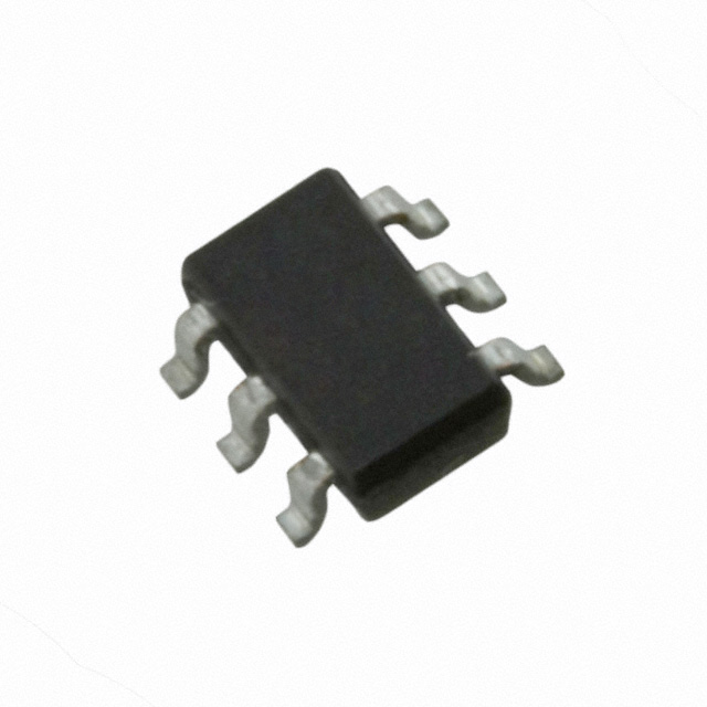
The IRF5800 is a P-Channel MOSFET manufactured by Infineon Technologies, rated for 30V drain-to-source voltage with 4A continuous drain current at 25°C. The device is packaged in Micro6™ (TSOP-6) surface mount configuration and belongs to the HEXFET® series. The IRF5800 is classified as obsolete, making equivalent and substitute parts necessary for new designs and ongoing production requirements. Substitute parts listed below maintain functional compatibility within specified electrical and mechanical parameters.
Substiute Parts
Key Parameters
| Parameter | Value | Unit |
|---|---|---|
| FET Type | P-Channel | — |
| Drain to Source Voltage (Vdss) | 30 | V |
| Current - Continuous Drain (Id) @ 25°C | 4 | A |
| Rds On (Max) @ Id, Vgs | 85 mOhm @ 4A, 10V | — |
| Vgs(th) (Max) @ Id | 1 | V @ 250µA |
| Gate Charge (Qg) (Max) @ Vgs | 17 | nC @ 10V |
| Power Dissipation (Max) | 2 | W |
| Operating Temperature Range | -55 to 150 | °C (TJ) |
| Mounting Type | Surface Mount | — |
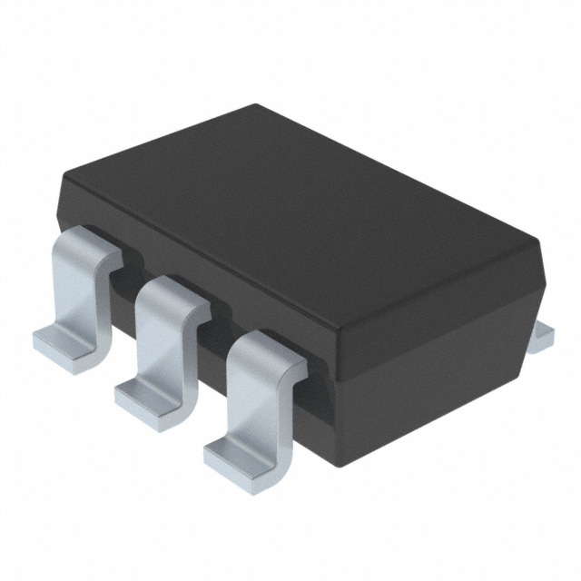
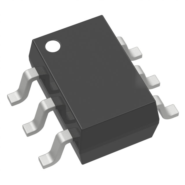
| Package | SOT-23-6 Thin, TSOP-6 | — |
Substitute Part Grouping Explanation
Substitute parts for the IRF5800 are selected based on strict electrical and mechanical parameter compatibility. The primary substitution criteria are:
Electrical Parameters:
- Drain-to-Source Voltage (Vdss): Must equal or exceed 30V
- Continuous Drain Current (Id): Must equal or exceed 4A at 25°C
- Gate-Source Voltage (Vgs): Must accommodate ±20V maximum rating
- On-State Resistance (Rds On): Lower values indicate improved performance; maximum acceptable value determined by application requirements
- Threshold Voltage (Vgs(th)): Must be compatible with drive circuitry
- Power Dissipation: Must support thermal requirements
Mechanical Parameters:
- Mounting Type: Surface Mount (all substitutes)
- Package Type: SOT-23-6 or TSOP-6 compatible footprints
- Pin Configuration: Must maintain functional pin compatibility
Substitutes are grouped by their ability to meet these criteria while maintaining active product status and current compliance certifications.
Parameter Comparison
| Parameter | IRF5800 | DMP3098LDM-7 | DMP3105LVT-7 | ZXM62P02E6TA | ZXMP3A17E6TA |
|---|---|---|---|---|---|
| Manufacturer | Infineon | Diodes Inc. | Diodes Inc. | Diodes Inc. | Diodes Inc. |
| Product Status | Obsolete | Active | Active | Active | Active |
| Vdss (V) | 30 | 30 | 30 | 20 | 30 |
| Id @ 25°C (A) | 4 | 4 | 3.1 | 2.3 | 3.2 |
| Rds On (Max) @ 10V (mOhm) | 85 | 65 | 75 | 200 | 70 |
| Vgs(th) (Max) @ 250µA (V) | 1 | 2.1 | 1.5 | 0.7 | 1 |
| Gate Charge (Qg) @ 10V (nC) | 17 | 7.8 | 19.8 | 5.8 | 15.8 |
| Power Dissipation (Max) (W) | 2 | 1.25 | 1.15 | 1.1 | 1.1 |
| Vgs (Max) (±V) | 20 | 20 | 12 | 12 | 20 |
| Package | SOT-23-6 Thin, TSOP-6 | SOT-23-6 | SOT-23-6 Thin, TSOP-26 | SOT-23-6 | SOT-23-6 |
| RoHS Status | Non-compliant | ROHS3 Compliant | ROHS3 Compliant | ROHS3 Compliant | ROHS3 Compliant |
Engineering Selection Recommendations
Primary Substitute: DMP3098LDM-7
The DMP3098LDM-7 from Diodes Incorporated provides the closest electrical match to the IRF5800. It maintains 30V Vdss rating and 4A continuous drain current specification. The device features improved on-state resistance (65 mOhm vs. 85 mOhm), lower gate charge (7.8 nC vs. 17 nC), and reduced power dissipation (1.25W vs. 2W). The DMP3098LDM-7 is ROHS3 compliant and carries active product status with substantial inventory availability (35,300 pcs). Package compatibility is maintained in SOT-23-6 configuration.
Secondary Substitute: ZXMP3A17E6TA
The ZXMP3A17E6TA offers 30V Vdss and 3.2A continuous drain current with 70 mOhm on-state resistance. This device maintains ±20V Vgs maximum rating, matching the IRF5800 specification. Gate charge is 15.8 nC, closer to the original device than DMP3098LDM-7. ROHS3 compliance and active product status are confirmed. Inventory availability is lower (8,790 pcs) compared to DMP3098LDM-7.
Tertiary Substitute: DMP3105LVT-7
The DMP3105LVT-7 maintains 30V Vdss rating with 3.1A continuous drain current. On-state resistance is 75 mOhm at 4.2A, 10V. This device features the highest gate charge (19.8 nC) among active substitutes but provides ROHS3 compliance and active product status. Vgs maximum rating is limited to ±12V, which may restrict compatibility with ±20V drive circuits. Inventory availability is highest (112,300 pcs).
Not Recommended: ZXM62P02E6TA
The ZXM62P02E6TA operates at reduced voltage (20V Vdss) and current (2.3A) ratings. While package and mounting type are compatible, the electrical specifications fall below IRF5800 requirements for applications requiring 30V operation or 4A current handling. This device is suitable only for applications with reduced voltage and current demands.
Frequently Asked Questions (FAQ)
Q: Can DMP3098LDM-7 directly replace IRF5800 in existing PCB layouts?
A: Yes, within package compatibility constraints. Both devices use SOT-23-6 surface mount packaging. Verify PCB footprint matches SOT-23-6 specifications. Pin configuration must be confirmed against schematic requirements.
Q: What is the impact of lower gate charge in DMP3098LDM-7 compared to IRF5800?
A: Lower gate charge (7.8 nC vs. 17 nC) reduces switching losses and allows faster switching transitions. This improves efficiency in switching applications and reduces heat generation. Drive circuit timing may require adjustment for optimal performance.
Q: Is ROHS3 compliance mandatory for substitute selection?
A: ROHS3 compliance is determined by application and regulatory requirements. All active substitutes listed (DMP3098LDM-7, DMP3105LVT-7, ZXMP3A17E6TA, ZXM62P02E6TA) are ROHS3 compliant. The original IRF5800 is non-compliant due to obsolete status.
Q: Why is ZXM62P02E6TA listed if it has lower voltage and current ratings?
A: ZXM62P02E6TA is included for applications where 20V operation and 2.3A current are sufficient. It is not suitable for designs requiring full 30V/4A specifications of the IRF5800.
Q: What is the significance of Vgs(th) differences between substitutes?
A: Vgs(th) determines the gate voltage required to turn the device on. IRF5800 requires 1V minimum at 250µA. DMP3098LDM-7 requires 2.1V, which may affect drive circuit design. Verify drive voltage compatibility with selected substitute.
Q: Can DMP3105LVT-7 be used in circuits designed for ±20V gate drive?
A: No. DMP3105LVT-7 has ±12V maximum Vgs rating. Applying ±20V gate voltage exceeds device specifications and may cause damage. Use only in circuits with ±12V or lower gate drive capability.
Q: Which substitute offers the best thermal performance?
A: DMP3098LDM-7 and ZXMP3A17E6TA both feature 1.1W to 1.25W power dissipation, lower than IRF5800 (2W). Lower power dissipation reduces thermal load on PCB and heat sink requirements.
Q: Is inventory availability a factor in substitute selection?
A: Inventory availability is provided for reference. DMP3105LVT-7 has highest availability (112,300 pcs), followed by DMP3098LDM-7 (35,300 pcs). Availability may vary by distributor and time of purchase.
Alternative Parts

SJ6012L2TP
Littelfuse Inc.
6 Alternative Parts

JMK107BBJ476MA-RE
Taiyo Yuden
10 Alternative Parts

GMK107BBJ475MA-T
Taiyo Yuden
5 Alternative Parts
SJ6020N2ARP
Littelfuse Inc.
3 Alternative Parts
SJ6025R2ATP
Littelfuse Inc.
4 Alternative Parts

2474-05L
API Delevan Inc.
1 Alternative Parts

4590R-684K
API Delevan Inc.
1 Alternative Parts

CM6560R-334
API Delevan Inc.
1 Alternative Parts

CM6460-104
API Delevan Inc.
1 Alternative Parts

5526-12
API Delevan Inc.
1 Alternative Parts