


Request Quote
(Ships tomorrow)
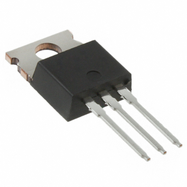
IRF540,127 N-Channel MOSFET 100V 23A TO-220AB Equivalent & Substitute Parts
Part Overview
The IRF540,127 is an N-Channel MOSFET manufactured by NXP USA Inc., rated for 100V drain-to-source voltage with 23A continuous drain current at 25°C. This device features the TrenchMOS™ series technology and is housed in a TO-220AB through-hole package. The part is classified as obsolete, making equivalent and substitute parts necessary for ongoing design support and procurement.
Substitute parts are selected based on matching electrical characteristics (Vdss, Id, Rds(on), gate charge, and operating temperature range) and mechanical compatibility (through-hole TO-220 package family). All substitutes maintain N-Channel MOSFET topology with 100V rating and comparable current handling capabilities.
Substiute Parts
Key Parameters
| Parameter | Value | Unit |
|---|---|---|
| FET Type | N-Channel | — |
| Drain to Source Voltage (Vdss) | 100 | V |
| Continuous Drain Current (Id) @ 25°C | 23 | A (Tc) |
| Drive Voltage (Max Rds On) | 10 | V |
| Rds(on) Max @ Id, Vgs | 77 | mOhm @ 17A, 10V |
| Gate Threshold Voltage Vgs(th) Max @ Id | 4 | V @ 1mA |
| Gate Charge (Qg) Max @ Vgs | 65 | nC @ 10V |
| Input Capacitance (Ciss) Max @ Vds | 1187 | pF @ 25V |
| Power Dissipation Max | 100 | W (Tc) |
| Operating Temperature Range | −55 to 175 | °C (TJ) |
| Mounting Type | Through Hole | — |
| Package / Case | TO-220-3 | — |
| Product Status | Obsolete | — |
| RoHS Status | ROHS3 Compliant | — |
Substitute Part Grouping Explanation
Substitution logic is based on the following electrical and mechanical criteria:
Primary Matching Criteria:
- Drain-to-Source Voltage (Vdss): 100V (exact match required)
- FET Type: N-Channel (exact match required)
- Technology: MOSFET Metal Oxide (exact match required)
- Operating Temperature Range: −55°C to 175°C (exact match required)
- Mounting Type: Through Hole (exact match required)
- Package Family: TO-220 (TO-220AB, TO-220-3, or equivalent through-hole variants)
Secondary Compatibility Parameters:
- Continuous Drain Current (Id): 5.6A minimum to 36A maximum (substitutes must support the application's current requirements)
- Rds(on) @ 10V: Comparable on-resistance characteristics
- Gate Charge (Qg): Affects switching speed and driver requirements
- Input Capacitance (Ciss): Influences gate drive circuit design
All seven substitute parts meet the primary matching criteria. Substitutes are grouped by current rating and on-resistance characteristics to facilitate selection based on specific application requirements.
Parameter Comparison
| Part Number | Manufacturer | Vdss (V) | Id @ 25°C (A) | Rds(on) Max (mOhm) | Qg Max (nC) | Ciss Max (pF) | Package | Status |
|---|---|---|---|---|---|---|---|---|
| IRF540,127 | NXP USA Inc. | 100 | 23 | 77 @ 17A, 10V | 65 @ 10V | 1187 @ 25V | TO-220AB | Obsolete |
| IRF510PBF | Vishay Siliconix | 100 | 5.6 | 540 @ 3.4A, 10V | 8.3 @ 10V | 180 @ 25V | TO-220AB | Active |
| IRF530NPBF | Infineon Technologies | 100 | 17 | 90 @ 9A, 10V | 37 @ 10V | 920 @ 25V | TO-220AB | Active |
| IRF540L | Vishay Siliconix | 100 | 28 | 77 @ 17A, 10V | 72 @ 10V | 1700 @ 25V | TO-262 | Active |
| IRF540NPBF | Infineon Technologies | 100 | 33 | 44 @ 16A, 10V | 71 @ 10V | 1960 @ 25V | TO-220AB | Active |
| IRF540PBF | Vishay Siliconix | 100 | 28 | 77 @ 17A, 10V | 72 @ 10V | 1700 @ 25V | TO-220AB | Active |
| IRF540ZPBF | Infineon Technologies | 100 | 36 | 26.5 @ 22A, 10V | 63 @ 10V | 1770 @ 25V | TO-220AB | Active |
| STP24NF10 | STMicroelectronics | 100 | 26 | 60 @ 12A, 10V | 41 @ 10V | 870 @ 25V | TO-220 | Active |
Engineering Selection Recommendations
For Direct Replacement (TO-220AB Package, Matched Current Rating):
IRF540PBF (Vishay Siliconix) and IRF540NPBF (Infineon Technologies) are the closest electrical equivalents to the IRF540,127. Both are rated for 28A to 33A continuous drain current, matching the original part's performance envelope. Both are ROHS3 compliant and active products with established supply chains. IRF540PBF is available in higher volume (19,734 pcs) and is REACH Affected. IRF540NPBF offers REACH Unaffected status with 85,300 pcs in stock.
For Enhanced Performance (Higher Current Rating):
IRF540ZPBF (Infineon Technologies, 36A, 26.5 mOhm) provides superior on-resistance and current handling. This part is suitable for applications requiring lower power dissipation or higher current margins. ROHS3 compliant, REACH Unaffected, with 17,422 pcs available.
For Lower Current Applications:
IRF530NPBF (Infineon Technologies, 17A) is appropriate for designs where the full 23A rating is not required. This part offers reduced gate charge (37 nC) and input capacitance (920 pF), resulting in faster switching characteristics and lower driver stress.
For Reduced Current Applications:
IRF510PBF (Vishay Siliconix, 5.6A) is suitable only for low-current designs. Higher on-resistance (540 mOhm) and significantly lower gate charge (8.3 nC) characterize this device.
For Alternative Packaging (TO-262):
IRF540L (Vishay Siliconix, 28A, TO-262) provides equivalent electrical performance in an alternative through-hole package. Note: This part is RoHS non-compliant and should be selected only when TO-262 packaging is a design requirement.
For Balanced Performance and Availability:
STP24NF10 (STMicroelectronics, 26A, STripFET™ II series) offers competitive on-resistance (60 mOhm), moderate gate charge (41 nC), and strong inventory (15,265 pcs). ROHS3 compliant and REACH Unaffected.
All recommended substitutes maintain the 100V Vdss rating, −55°C to 175°C operating temperature range, and through-hole mounting configuration. Selection should be based on specific application current requirements, thermal management constraints, and compliance certifications.
Frequently Asked Questions (FAQ)
Q: Can IRF510PBF replace IRF540,127 in all applications?
A: No. IRF510PBF is rated for only 5.6A continuous drain current, compared to the IRF540,127's 23A rating. This substitute is suitable only for low-current applications where the original part's current capacity is not required. The significantly higher on-resistance (540 mOhm vs. 77 mOhm) will result in greater power dissipation.
Q: What is the difference between IRF540PBF and IRF540NPBF?
A: Both parts are electrically equivalent with 28A to 33A ratings and 100V Vdss. The primary differences are manufacturer (Vishay vs. Infineon), REACH compliance status (Affected vs. Unaffected), and inventory availability. IRF540NPBF has higher stock levels (85,300 pcs vs. 19,734 pcs).
Q: Is IRF540L a direct replacement for IRF540,127?
A: IRF540L is electrically compatible but uses a different package (TO-262 vs. TO-220AB). PCB layout and thermal management design must be re-evaluated. Additionally, IRF540L is RoHS non-compliant, which may conflict with design or procurement requirements.
Q: Why does IRF540ZPBF have lower on-resistance than the original part?
A: IRF540ZPBF is rated for 36A continuous drain current, compared to IRF540,127's 23A. The lower on-resistance (26.5 mOhm vs. 77 mOhm) reflects improved die technology and larger silicon area, enabling higher current handling with reduced power dissipation.
Q: Can I use STP24NF10 as a substitute?
A: Yes. STP24NF10 is rated for 26A, matching the original part's current envelope. It features lower on-resistance (60 mOhm) and moderate gate charge (41 nC). The STripFET™ II technology provides good switching characteristics. All compliance certifications (ROHS3, REACH Unaffected) are met.
Q: What should I consider when selecting between multiple substitutes?
A: Evaluate application requirements for (1) continuous drain current: select a part rated at or above your circuit's maximum current; (2) on-resistance: lower values reduce power dissipation and heat generation; (3) gate charge: affects switching speed and driver circuit design; (4) package compatibility: ensure PCB layout accommodates the selected package; (5) compliance certifications: verify RoHS and REACH status against procurement requirements; (6) supply chain: confirm inventory availability and lead times.
Q: Are all substitutes rated for the same operating temperature range?
A: Yes. All substitute parts listed are rated for −55°C to 175°C junction temperature, matching the IRF540,127's operating range.
Q: What is the significance of gate charge (Qg) differences?
A: Gate charge affects the energy required to switch the MOSFET on and off. Lower gate charge (e.g., IRF510PBF at 8.3 nC) requires less driver current and enables faster switching. Higher gate charge (e.g., IRF540NPBF at 71 nC) may require a more robust gate driver but provides better noise immunity in some applications.
Alternative Parts

SJ6012L2TP
Littelfuse Inc.
6 Alternative Parts

JMK107BBJ476MA-RE
Taiyo Yuden
10 Alternative Parts

GMK107BBJ475MA-T
Taiyo Yuden
5 Alternative Parts
SJ6020N2ARP
Littelfuse Inc.
3 Alternative Parts
SJ6025R2ATP
Littelfuse Inc.
4 Alternative Parts

2474-05L
API Delevan Inc.
1 Alternative Parts

4590R-684K
API Delevan Inc.
1 Alternative Parts

CM6560R-334
API Delevan Inc.
1 Alternative Parts

CM6460-104
API Delevan Inc.
1 Alternative Parts

5526-12
API Delevan Inc.
1 Alternative Parts