


Request Quote
(Ships tomorrow)
IRF2804STRL N-Channel 40V 75A MOSFET Equivalent & Substitute Parts
Part Overview
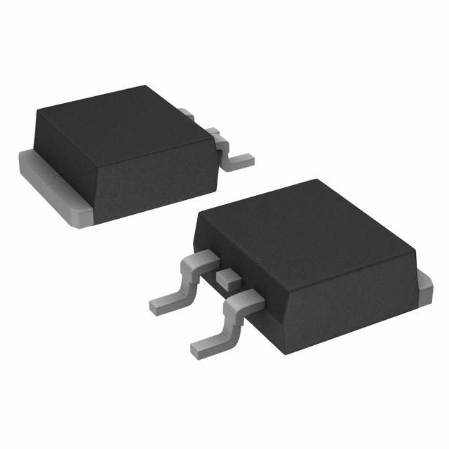
The IRF2804STRL is an N-Channel MOSFET manufactured by Infineon Technologies, designed for surface mount applications in the D2PAK package. This device operates at 40V drain-to-source voltage with a continuous drain current rating of 75A at 25°C and maximum power dissipation of 330W. The IRF2804STRL is classified as obsolete product status, making equivalent and substitute parts necessary for ongoing design support and procurement continuity. The IRF2804STRLPBF represents the active production variant with identical electrical specifications but improved RoHS compliance status.
Substiute Parts
Key Parameters
| Parameter | Value | Unit |
|---|---|---|
| Drain-to-Source Voltage (Vdss) | 40 | V |
| Continuous Drain Current (Id) @ 25°C | 75 | A |
| On-State Resistance (Rds On) @ 75A, 10V | 2 | mOhm |
| Gate-Source Threshold Voltage (Vgs(th)) @ 250µA | 4 | V |
| Gate Charge (Qg) @ 10V | 240 | nC |
| Maximum Power Dissipation (Tc) | 330 | W |
| Operating Temperature Range | -55 to 175 | °C |
| Package Type | D2PAK (TO-263-3) | Surface Mount |
| FET Technology | Metal Oxide (MOSFET) | N-Channel |
Substitute Part Grouping Explanation
Substitution of the IRF2804STRL is determined by strict adherence to the following electrical and mechanical parameters:
Primary Substitution Criteria:
- Drain-to-Source Voltage (Vdss): Must equal or exceed 40V
- Package Type: Must be D2PAK (TO-263-3) or compatible surface mount variant
- Operating Temperature Range: Must support -55°C to 175°C minimum
- Mounting Type: Surface mount configuration required
- Continuous Drain Current (Id): Minimum 75A at 25°C
Secondary Compatibility Parameters:
- On-State Resistance (Rds On): Lower or equal values indicate improved performance
- Gate Charge (Qg): Lower values reduce switching losses
- Power Dissipation: Equal or greater ratings ensure thermal compatibility
- Vgs(th): Must fall within acceptable gate drive voltage range
Substitute parts are grouped into two categories: direct replacements with identical or superior electrical specifications, and functional equivalents with enhanced current-handling or power dissipation capabilities that maintain full backward compatibility within the D2PAK package constraint.
Parameter Comparison
| Part Number | Manufacturer | Vdss (V) | Id @ 25°C (A) | Rds On (mOhm) | Qg (nC) | Pd Max (W) | Package | Status | RoHS |
|---|---|---|---|---|---|---|---|---|---|
| IRF2804STRL | Infineon | 40 | 75 | 2.0 | 240 | 330 | D2PAK | Obsolete | Non-compliant |
| IRF2804STRLPBF | Infineon | 40 | 75 | 2.0 | 240 | 300 | D2PAK | Active | ROHS3 |
| BUK661R9-40C,118 | Nexperia | 40 | 120 | 1.9 | 260 | 306 | D2PAK | Obsolete | ROHS3 |
| IXTA300N04T2 | IXYS | 40 | 300 | 2.5 | 145 | 480 | TO-263AA | Active | ROHS3 |
| PSMN1R1-40BS,118 | Nexperia | 40 | 120 | 1.3 | 136 | 306 | D2PAK | Active | ROHS3 |
| PSMN2R2-40BS,118 | Nexperia | 40 | 100 | 2.2 | 130 | 306 | D2PAK | Active | ROHS3 |
| SQM120N04-1M7_GE3 | Vishay | 40 | 120 | 1.7 | 310 | 300 | D2PAK | Active | ROHS3 |
| STB270N4F3 | STMicroelectronics | 40 | 160 | 2.5 | 150 | 330 | D2PAK | Active | ROHS3 |
Engineering Selection Recommendations
Direct Replacement (Preferred for Obsolete Part Mitigation):
IRF2804STRLPBF is the recommended primary substitute. This part maintains identical electrical specifications to the IRF2804STRL while offering active product status and ROHS3 compliance. The packaging, thermal characteristics, and gate drive requirements are fully compatible. Inventory availability is significantly higher (47,468 units in stock versus 710 units for the obsolete variant).
Enhanced Performance Substitutes (Active Status, Improved Specifications):
PSMN1R1-40BS,118 (Nexperia) provides superior on-state resistance (1.3 mOhm versus 2.0 mOhm) and reduced gate charge (136 nC versus 240 nC), resulting in lower switching losses and improved thermal performance. Continuous drain current rating of 120A exceeds the 75A requirement. Active product status and ROHS3 compliance are confirmed. D2PAK package maintains mechanical compatibility.
STB270N4F3 (STMicroelectronics) offers the highest current capability (160A) with matching power dissipation (330W) and identical Vdss rating. Gate charge of 150 nC provides moderate switching loss reduction. Active status and ROHS3 compliance are confirmed. D2PAK package is compatible. Automotive qualification (AEC-Q101) is available.
PSMN2R2-40BS,118 (Nexperia) supports 100A continuous drain current with reduced gate charge (130 nC). On-state resistance of 2.2 mOhm is slightly higher than the original specification. Active status and ROHS3 compliance are confirmed. D2PAK package is compatible.
High-Current Alternative (Performance Enhancement):
IXTA300N04T2 (IXYS) provides exceptional current handling (300A) and power dissipation (480W) with reduced gate charge (145 nC). This part is suitable for applications requiring significant thermal or current margin. Package designation is TO-263AA, which is mechanically compatible with D2PAK. Active status and ROHS3 compliance are confirmed.
Selection Criteria Summary:
- For direct replacement with minimal design changes: IRF2804STRLPBF
- For improved efficiency and reduced switching losses: PSMN1R1-40BS,118
- For maximum current capability and thermal headroom: STB270N4F3 or IXTA300N04T2
- For automotive applications: STB270N4F3 (AEC-Q101 qualified)
All recommended substitutes maintain the 40V Vdss rating, D2PAK or compatible surface mount packaging, and -55°C to 175°C operating temperature range.
Frequently Asked Questions (FAQ)
Q: Can IRF2804STRLPBF be used as a direct replacement for IRF2804STRL?
A: Yes. IRF2804STRLPBF is the active production equivalent with identical electrical specifications (40V, 75A, 2 mOhm Rds On, 240 nC gate charge). The primary differences are product status (active versus obsolete) and RoHS compliance (ROHS3 versus non-compliant). Packaging, pinout, and thermal characteristics are identical. No circuit modifications are required.
Q: What is the key difference between the IRF2804STRL and PSMN1R1-40BS,118?
A: Both devices share the same 40V Vdss rating and D2PAK package. The PSMN1R1-40BS,118 provides higher continuous drain current (120A versus 75A), lower on-state resistance (1.3 mOhm versus 2.0 mOhm), and significantly reduced gate charge (136 nC versus 240 nC). These improvements result in lower conduction losses and faster switching characteristics. The PSMN1R1-40BS,118 is active status with ROHS3 compliance.
Q: Are all substitute parts compatible with the D2PAK package footprint?
A: Yes. All listed substitutes use D2PAK (TO-263-3) or TO-263AA packaging, which share identical lead spacing and mounting footprints. The IXTA300N04T2 uses TO-263AA designation but maintains full mechanical compatibility with D2PAK PCB layouts. No footprint modifications are required for any substitute.
Q: Which substitute offers the best thermal performance?
A: IXTA300N04T2 provides the highest power dissipation rating (480W) and lowest gate charge (145 nC), resulting in superior thermal performance and reduced switching losses. STB270N4F3 offers matching power dissipation (330W) to the original IRF2804STRL with improved current capability (160A). Both are active status with ROHS3 compliance.
Q: Can I use a substitute with higher continuous drain current rating?
A: Yes. Substitutes with higher current ratings (PSMN1R1-40BS,118 at 120A, STB270N4F3 at 160A, IXTA300N04T2 at 300A) are fully compatible and provide additional design margin. The 40V Vdss rating, gate drive voltage requirements, and package compatibility remain unchanged. Higher current capability does not introduce compatibility issues in applications designed for 75A operation.
Q: What is the significance of gate charge (Qg) differences?
A: Gate charge directly affects switching speed and power loss in the gate drive circuit. Lower gate charge values (PSMN1R1-40BS,118 at 136 nC, PSMN2R2-40BS,118 at 130 nC) reduce switching losses and allow faster switching frequencies. The original IRF2804STRL specifies 240 nC. Substitutes with lower Qg values improve overall circuit efficiency but require no circuit modifications for compatibility.
Q: Are automotive-qualified alternatives available?
A: Yes. STB270N4F3 carries AEC-Q101 automotive qualification and SQM120N04-1M7_GE3 carries AEC-Q101 qualification. Both maintain 40V Vdss, D2PAK packaging, and -55°C to 175°C operating temperature range. These parts are suitable for automotive applications requiring formal qualification documentation.
Q: What is the difference between Tape & Reel (TR) and Cut Tape (CT) packaging?
A: Tape & Reel packaging is supplied on continuous reels for automated assembly processes. Cut Tape & Digi-Reel packaging is supplied in smaller quantities on tape segments. Both formats contain identical components with identical electrical specifications. Selection depends on production volume and assembly equipment compatibility, not electrical performance.
Q: Can I mix different substitute parts in the same design?
A: Yes. All listed substitutes maintain the same 40V Vdss rating, D2PAK package, and -55°C to 175°C operating temperature range. Mixing different part numbers in the same circuit is electrically compatible. However, variations in on-state resistance and gate charge may result in slightly different switching characteristics and thermal distribution across components. Consistent part selection within a design is recommended for uniform performance.
Q: What is the impact of lower on-state resistance (Rds On)?
A: Lower on-state resistance reduces conduction losses (I²R losses) during normal operation, resulting in lower heat generation and improved efficiency. PSMN1R1-40BS,118 at 1.3 mOhm provides approximately 35% lower conduction losses compared to the original 2.0 mOhm specification. This improvement is beneficial in high-current applications but requires no circuit modifications for compatibility.
Alternative Parts

SJ6012L2TP
Littelfuse Inc.
6 Alternative Parts

JMK107BBJ476MA-RE
Taiyo Yuden
10 Alternative Parts

GMK107BBJ475MA-T
Taiyo Yuden
5 Alternative Parts
SJ6020N2ARP
Littelfuse Inc.
3 Alternative Parts
SJ6025R2ATP
Littelfuse Inc.
4 Alternative Parts

2474-05L
API Delevan Inc.
1 Alternative Parts

4590R-684K
API Delevan Inc.
1 Alternative Parts

CM6560R-334
API Delevan Inc.
1 Alternative Parts

CM6460-104
API Delevan Inc.
1 Alternative Parts

5526-12
API Delevan Inc.
1 Alternative Parts