


Request Quote
(Ships tomorrow)
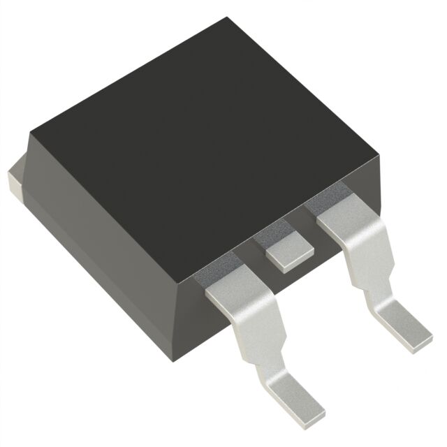
IRF1405S N-Channel MOSFET 55V 131A D2PAK Equivalent & Substitute Parts
Part Overview
The IRF1405S is an N-Channel MOSFET manufactured by Infineon Technologies, rated for 55V drain-to-source voltage with 131A continuous drain current at 25°C. This device is housed in a D2PAK (TO-263-3) surface mount package and is part of the HEXFET® series. The IRF1405S is classified as obsolete, which necessitates identification of equivalent and substitute components for new designs and ongoing production requirements. Substitute parts must maintain electrical compatibility within the specified parameter ranges while meeting current manufacturing and compliance standards.
Substiute Parts
Key Parameters
| Parameter | Value | Unit | Condition |
|---|---|---|---|
| Drain-to-Source Voltage (Vdss) | 55 | V | Maximum rating |
| Continuous Drain Current (Id) @ 25°C | 131 | A | Tc (case temperature) |
| On-State Resistance (Rds On) | 5.3 | mOhm | @ 101A, 10V Vgs |
| Gate Threshold Voltage (Vgs(th)) | 4 | V | @ 250µA Id |
| Gate Charge (Qg) | 260 | nC | @ 10V Vgs |
| Power Dissipation (Max) | 200 | W | Tc |
| Operating Temperature Range | -55 to 175 | °C | TJ (junction) |
| Package Type | D2PAK | TO-263-3 | Surface mount |
Substitute Part Grouping Explanation
Substitution of the IRF1405S is determined by the following critical electrical and mechanical parameters:
Voltage Rating: All substitute parts must have a Vdss rating of 55V or higher to ensure safe operation within the original design envelope.
Current Capability: The continuous drain current (Id) at 25°C must be sufficient to handle the application load. Substitutes with Id ratings from 75A to 131A are acceptable, with higher ratings providing design margin.
On-State Resistance (Rds On): This parameter directly affects power dissipation and thermal performance. Substitutes with Rds On values between 4.4 mOhm and 6.5 mOhm maintain comparable switching losses.
Gate Charge (Qg): Lower gate charge values reduce driver power requirements and switching losses. Acceptable range is 70.8 nC to 260 nC.
Package Compatibility: All substitutes must use D2PAK (TO-263-3) surface mount packaging to ensure mechanical and thermal interface compatibility.
Operating Temperature: All substitutes must support the -55°C to 175°C temperature range.
Compliance Status: Active or Last Time Buy status is preferred over obsolete classification. RoHS3 compliance is required for new designs.
Parameter Comparison
| Part Number | Manufacturer | Vdss (V) | Id @ 25°C (A) | Rds On (mOhm) | Qg (nC) | Pd Max (W) | Status | RoHS |
|---|---|---|---|---|---|---|---|---|
| IRF1405S | Infineon | 55 | 131 | 5.3 | 260 | 200 | Obsolete | Non-compliant |
| IRF1405STRLPBF | Infineon | 55 | 131 | 5.3 | 260 | 200 | Active | ROHS3 |
| STB150NF55T4 | STMicroelectronics | 55 | 120 | 6.0 | 190 | 300 | Active | ROHS3 |
| STB80NF55-06T4 | STMicroelectronics | 55 | 80 | 6.5 | 189 | 300 | Active | ROHS3 |
| BUK7610-55AL,118 | Nexperia | 55 | 75 | 10.0 | 124 | 300 | Obsolete | ROHS3 |
| PSMN4R6-60BS,118 | Nexperia | 60 | 100 | 4.4 | 70.8 | 211 | Active | ROHS3 |
| IPB054N06N3GATMA1 | Infineon | 60 | 80 | 5.4 | 82 | 115 | Last Time Buy | ROHS3 |
Engineering Selection Recommendations
Primary Substitute (Direct Replacement):
IRF1405STRLPBF is the recommended primary substitute. This part is electrically identical to the IRF1405S with matching Vdss (55V), Id (131A), Rds On (5.3 mOhm), and Qg (260 nC). The critical distinction is product status: IRF1405STRLPBF is Active and RoHS3 compliant, whereas the original IRF1405S is obsolete and RoHS non-compliant. The tape and reel packaging (TRLPBF designation) is suitable for automated assembly processes. This substitute requires no circuit redesign or thermal management modifications.
Secondary Substitutes (Electrical Compatibility with Design Considerations):
STB150NF55T4 (STMicroelectronics, STripFET™ II series) maintains the 55V voltage rating with 120A continuous current, representing a 91.6% current capability relative to the IRF1405S. The Rds On of 6.0 mOhm is slightly higher, resulting in approximately 13% increased conduction losses. Gate charge is reduced to 190 nC, improving switching performance. Power dissipation rating increases to 300W, providing superior thermal headroom. This part is Active and RoHS3 compliant.
STB80NF55-06T4 (STMicroelectronics, STripFET™ II series) provides 80A continuous current at 55V, suitable for applications with reduced current requirements. Rds On of 6.5 mOhm and gate charge of 189 nC are comparable to STB150NF55T4. The 300W power dissipation rating supports high-frequency switching applications. This part is Active and RoHS3 compliant.
PSMN4R6-60BS,118 (Nexperia) offers 60V voltage rating with 100A continuous current. The superior Rds On of 4.4 mOhm reduces conduction losses by approximately 17% compared to the IRF1405S. Gate charge of 70.8 nC is the lowest among substitutes, minimizing driver power requirements. Power dissipation is rated at 211W. The 5V higher voltage rating provides additional design margin. This part is Active and RoHS3 compliant.
Substitutes with Limitations:
BUK7610-55AL,118 (Nexperia, TrenchMOS™ series) matches the 55V rating but provides only 75A continuous current. The Rds On of 10.0 mOhm is significantly higher, resulting in approximately 89% increased conduction losses. This part is classified as obsolete despite RoHS3 compliance and is not recommended for new designs.
IPB054N06N3GATMA1 (Infineon, OptiMOS™ series) has a 60V rating with 80A continuous current. The power dissipation rating of 115W is substantially lower than the IRF1405S, limiting thermal performance in high-power applications. This part is classified as Last Time Buy, indicating end-of-life status.
Compliance and Availability:
All recommended substitutes are RoHS3 compliant and support the full -55°C to 175°C operating temperature range. IRF1405STRLPBF has the highest inventory availability (1680 pcs) among direct equivalents. STB150NF55T4 and STB80NF55-06T4 have substantial inventory (10200 and 15465 pcs respectively), ensuring supply continuity. PSMN4R6-60BS,118 has the highest inventory level (11246 pcs) among all substitutes.
Frequently Asked Questions (FAQ)
Q: Can IRF1405STRLPBF be used as a direct drop-in replacement for IRF1405S?
A: Yes. IRF1405STRLPBF is electrically and mechanically identical to IRF1405S. Both devices have 55V Vdss, 131A continuous drain current, 5.3 mOhm Rds On, and D2PAK packaging. The primary difference is product status: IRF1405STRLPBF is Active and RoHS3 compliant. No circuit modifications are required.
Q: What is the impact of using STB150NF55T4 instead of IRF1405S?
A: STB150NF55T4 has 120A continuous current versus 131A for IRF1405S, representing 91.6% current capability. Rds On increases from 5.3 mOhm to 6.0 mOhm, increasing conduction losses by approximately 13%. Gate charge decreases from 260 nC to 190 nC, improving switching speed. Power dissipation rating increases from 200W to 300W. These characteristics are acceptable for most applications with adequate thermal design.
Q: Why does PSMN4R6-60BS,118 have a higher voltage rating (60V) than IRF1405S (55V)?
A: The 60V Vdss rating on PSMN4R6-60BS,118 provides additional design margin and safety headroom. A 60V-rated device can safely operate in circuits designed for 55V maximum. The higher voltage rating does not create compatibility issues; it only extends the safe operating envelope.
Q: Is the D2PAK package identical across all substitute parts?
A: Yes. All substitute parts use D2PAK (TO-263-3) surface mount packaging with identical pin configuration and thermal interface. PCB footprints and thermal vias designed for IRF1405S are directly compatible with all listed substitutes.
Q: What does "Last Time Buy" status mean for IPB054N06N3GATMA1?
A: Last Time Buy indicates the manufacturer has announced end-of-life for this part. Customers have a final opportunity to purchase inventory before production ceases. This part should not be selected for new designs requiring long-term supply continuity.
Q: How does gate charge affect circuit performance?
A: Gate charge (Qg) determines the energy required to switch the MOSFET on and off. Lower gate charge reduces driver power consumption and enables faster switching transitions. PSMN4R6-60BS,118 has the lowest gate charge (70.8 nC), while IRF1405S has the highest (260 nC). For high-frequency applications, lower gate charge is advantageous.
Q: Can I use a substitute with lower continuous current rating?
A: Substitutes with lower Id ratings (such as STB80NF55-06T4 at 80A versus IRF1405S at 131A) are acceptable only if the application's maximum current requirement does not exceed the substitute's rating. Circuit analysis must confirm that peak and continuous currents remain within the substitute's specifications.
Q: What is the significance of RoHS3 compliance?
A: RoHS3 compliance indicates the part meets Restriction of Hazardous Substances regulations, restricting lead, cadmium, mercury, and other hazardous materials. RoHS3 compliance is mandatory for new designs and products sold in regulated markets. The original IRF1405S is RoHS non-compliant and cannot be used in new designs subject to RoHS requirements.
Q: Are there thermal management differences between substitutes?
A: Yes. Power dissipation ratings vary: IRF1405S (200W), STB150NF55T4 (300W), STB80NF55-06T4 (300W), PSMN4R6-60BS,118 (211W), and IPB054N06N3GATMA1 (115W). Higher power dissipation ratings indicate better thermal performance. Rds On values also affect thermal performance: lower Rds On generates less heat during conduction. Thermal design must account for both factors.
Alternative Parts

SJ6012L2TP
Littelfuse Inc.
6 Alternative Parts

JMK107BBJ476MA-RE
Taiyo Yuden
10 Alternative Parts

GMK107BBJ475MA-T
Taiyo Yuden
5 Alternative Parts
SJ6020N2ARP
Littelfuse Inc.
3 Alternative Parts
SJ6025R2ATP
Littelfuse Inc.
4 Alternative Parts

2474-05L
API Delevan Inc.
1 Alternative Parts

4590R-684K
API Delevan Inc.
1 Alternative Parts

CM6560R-334
API Delevan Inc.
1 Alternative Parts

CM6460-104
API Delevan Inc.
1 Alternative Parts

5526-12
API Delevan Inc.
1 Alternative Parts