


Request Quote
(Ships tomorrow)
IRF1404ZSTRL N-Channel 40V 180A MOSFET Equivalent & Substitute Parts
Part Overview
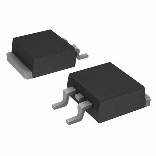
The IRF1404ZSTRL is an N-Channel MOSFET manufactured by Infineon Technologies, rated for 40V drain-to-source voltage and 180A continuous drain current in a D2PAK surface mount package. This part is classified as obsolete, which necessitates identification of functionally equivalent alternatives for new designs and ongoing production support. The IRF1404ZSTRL operates across a temperature range of -55°C to 175°C and dissipates up to 220W at the case temperature (Tc).
Substitute parts must maintain electrical compatibility across voltage ratings, current handling capacity, gate drive characteristics, and thermal performance while conforming to the same D2PAK package footprint.
Substiute Parts
Key Parameters
| Parameter | Value | Unit | Specification Basis |
|---|---|---|---|
| Drain-to-Source Voltage (Vdss) | 40 | V | Maximum rated voltage |
| Continuous Drain Current (Id) @ 25°C | 180 | A (Tc) | Case temperature rating |
| On-State Resistance (Rds On) @ 75A, 10V | 3.7 | mOhm | Maximum at specified gate voltage |
| Gate Threshold Voltage (Vgs(th)) @ 250µA | 4 | V | Maximum threshold |
| Gate Charge (Qg) @ 10V | 150 | nC | Maximum gate charge |
| Power Dissipation (Max) | 220 | W (Tc) | Case temperature rating |
| Operating Temperature Range | -55 to 175 | °C (TJ) | Junction temperature |
| Package Type | D2PAK (TO-263-3) | Surface Mount | 2 Leads + Tab |
Substitute Part Grouping Explanation
Substitution eligibility for the IRF1404ZSTRL is determined by the following criteria:
Primary Compatibility Requirements:
- Drain-to-Source Voltage (Vdss): Must equal 40V
- Package Type: Must be D2PAK (TO-263-3) for mechanical and thermal compatibility
- FET Type: Must be N-Channel MOSFET
- Operating Temperature Range: Must support -55°C to 175°C
Secondary Performance Parameters:
- Continuous Drain Current (Id): Substitute must support minimum 180A at Tc, or lower current rating if application permits
- On-State Resistance (Rds On): Lower or equal values indicate improved performance
- Gate Charge (Qg): Lower values reduce drive circuit complexity
- Power Dissipation: Must support thermal requirements of the application
Compliance Considerations:
- RoHS Status: Active substitutes should be RoHS3 compliant
- Product Status: Active or Not For New Designs status preferred over obsolete
- Automotive Grade: AEC-Q101 qualification indicates enhanced reliability
The following substitute parts meet the primary compatibility requirements and are grouped by current rating and product status.
Parameter Comparison
| Parameter | IRF1404ZSTRL (Main) | IRF1404ZSTRLPBF | BUK964R4-40B,118 | STB120N4F6 | SUM110N04-04-E3 | AOB240L |
|---|---|---|---|---|---|---|
| Manufacturer | Infineon | Infineon | Nexperia | STMicroelectronics | Vishay Siliconix | Alpha & Omega |
| Vdss (V) | 40 | 40 | 40 | 40 | 40 | 40 |
| Id @ 25°C (A, Tc) | 180 | 180 | 75 | 80 | 110 | 105 |
| Rds On (mOhm) @ 10V | 3.7 @ 75A | 3.7 @ 75A | 4.0 @ 25A | 4.0 @ 40A | 3.5 @ 30A | 2.6 @ 20A |
| Vgs(th) (V) | 4 @ 250µA | 4 @ 150µA | 2 @ 1mA | 4 @ 250µA | 4 @ 250µA | 2.2 @ 250µA |
| Qg (nC) @ 10V | 150 | 150 | 64 | 65 | 200 | 72 |
| Ciss (pF) @ 25V | 4340 | 4340 | 7124 | 3850 | 6800 | 3510 |
| Power Dissipation (W, Tc) | 220 | 200 | 254 | 110 | 250 | 176 |
| Operating Temp (°C) | -55 to 175 | -55 to 175 | -55 to 175 | -55 to 175 | -55 to 175 | -55 to 175 |
| Package | D2PAK | D2PAK | D2PAK | D2PAK | D2PAK | D2PAK |
| Product Status | Obsolete | Active | Active | Active | Active | Not For New Designs |
| RoHS Status | Non-compliant | ROHS3 Compliant | ROHS3 Compliant | ROHS3 Compliant | ROHS3 Compliant | ROHS3 Compliant |
| Automotive Grade | No | No | Yes (AEC-Q101) | Yes (AEC-Q101) | No | No |
Engineering Selection Recommendations
Direct Replacement (Highest Compatibility):
IRF1404ZSTRLPBF is the primary substitute for IRF1404ZSTRL. Both parts are manufactured by Infineon Technologies and share identical electrical specifications: 40V Vdss, 180A continuous drain current, 3.7mOhm Rds On at 75A/10V, and D2PAK packaging. The IRF1404ZSTRLPBF is classified as Active product status with ROHS3 compliance, addressing the obsolescence of the original part. Packaging differs only in supplier format (Cut Tape & Digi-Reel® versus standard), with no impact on electrical or mechanical performance.
High-Current Alternatives (Current Rating ≥ 110A):
SUM110N04-04-E3 (Vishay Siliconix, 110A) and BUK964R4-40B,118 (Nexperia, 75A) provide reduced current ratings compared to the IRF1404ZSTRL but maintain 40V Vdss and D2PAK packaging. SUM110N04-04-E3 offers 110A continuous current with superior on-state resistance (3.5mOhm @ 30A/10V) and higher power dissipation (250W Tc). BUK964R4-40B,118 is AEC-Q101 qualified for automotive applications and features lower gate charge (64nC @ 5V) for faster switching. Both are Active status with ROHS3 compliance.
Moderate-Current Alternatives (Current Rating 80-105A):
STB120N4F6 (STMicroelectronics, 80A) and AOB240L (Alpha & Omega, 105A) are suitable for applications where the full 180A rating is not required. STB120N4F6 is AEC-Q101 qualified with Active status and lower input capacitance (3850pF @ 25V). AOB240L carries Not For New Designs status but offers 105A continuous current with the lowest on-state resistance among substitutes (2.6mOhm @ 20A/10V).
Product Status Hierarchy:
- Preferred: Active status (IRF1404ZSTRLPBF, BUK964R4-40B,118, STB120N4F6, SUM110N04-04-E3)
- Secondary: Not For New Designs (AOB240L)
- Avoid: Obsolete (IRF1404ZSTRL)
Compliance Considerations: All substitute parts are ROHS3 compliant and REACH unaffected. BUK964R4-40B,118 and STB120N4F6 carry AEC-Q101 automotive qualification, suitable for automotive and high-reliability applications.
Frequently Asked Questions (FAQ)
Q: Can IRF1404ZSTRLPBF be used as a direct replacement for IRF1404ZSTRL?
A: Yes. IRF1404ZSTRLPBF is electrically and mechanically identical to IRF1404ZSTRL. Both feature 40V Vdss, 180A continuous drain current, 3.7mOhm Rds On, and D2PAK packaging. The primary difference is product status: IRF1404ZSTRLPBF is Active with ROHS3 compliance, while IRF1404ZSTRL is obsolete and RoHS non-compliant. Packaging format (Cut Tape & Digi-Reel® versus standard) does not affect electrical performance.
Q: What is the minimum current rating acceptable for a substitute?
A: Substitute selection depends on application requirements. If the circuit operates at continuous drain currents below 180A, lower-rated alternatives are acceptable. For example, STB120N4F6 (80A) is suitable for applications requiring ≤80A. However, if the application demands the full 180A rating, only IRF1404ZSTRLPBF provides equivalent performance.
Q: Are all substitute parts compatible with the D2PAK footprint?
A: Yes. All listed substitutes use the D2PAK (TO-263-3) package with identical pin configuration (2 Leads + Tab). No PCB layout modifications are required for mechanical compatibility.
Q: Which substitute is recommended for automotive applications?
A: BUK964R4-40B,118 and STB120N4F6 both carry AEC-Q101 automotive qualification. BUK964R4-40B,118 is rated for 75A continuous current, while STB120N4F6 is rated for 80A. Both are Active status with ROHS3 compliance and suitable for automotive-grade designs.
Q: What is the significance of on-state resistance (Rds On) differences?
A: Lower Rds On values reduce power dissipation and heat generation during operation. SUM110N04-04-E3 (3.5mOhm @ 30A/10V) and AOB240L (2.6mOhm @ 20A/10V) exhibit lower Rds On than the original IRF1404ZSTRL (3.7mOhm @ 75A/10V). However, Rds On is measured at different current levels, so direct comparison requires evaluation at the specific operating point of the application.
Q: Does gate charge (Qg) affect circuit design?
A: Yes. Gate charge determines the energy required to switch the MOSFET and influences gate driver selection. Lower Qg values (BUK964R4-40B,118 at 64nC, STB120N4F6 at 65nC) reduce gate drive circuit complexity compared to higher values (SUM110N04-04-E3 at 200nC). The original IRF1404ZSTRL specifies 150nC @ 10V.
Q: Why is AOB240L marked as "Not For New Designs"?
A: AOB240L carries Not For New Designs status, indicating the manufacturer recommends against use in new product development. However, it remains available for legacy system support and maintenance. For new designs, prioritize Active status alternatives such as IRF1404ZSTRLPBF, BUK964R4-40B,118, STB120N4F6, or SUM110N04-04-E3.
Q: What is the impact of input capacitance (Ciss) on substitution?
A: Input capacitance affects gate drive circuit performance and switching speed. Substitutes exhibit varying Ciss values: STB120N4F6 (3850pF @ 25V) and AOB240L (3510pF @ 20V) are lower than IRF1404ZSTRL (4340pF @ 25V), while BUK964R4-40B,118 (7124pF @ 25V) and SUM110N04-04-E3 (6800pF @ 25V) are higher. Higher Ciss requires stronger gate drivers but does not prevent substitution if the gate driver is adequately rated.
Q: Are there thermal considerations when selecting a substitute?
A: Yes. Power dissipation ratings vary among substitutes. IRF1404ZSTRLPBF (200W Tc) and STB120N4F6 (110W Tc) dissipate less power than the original IRF1404ZSTRL (220W Tc), while SUM110N04-04-E3 (250W Tc) and BUK964R4-40B,118 (254W Tc) dissipate more. Thermal design must account for the substitute's power dissipation and ensure adequate heat sinking for the application's operating conditions.
Alternative Parts

SJ6012L2TP
Littelfuse Inc.
6 Alternative Parts

JMK107BBJ476MA-RE
Taiyo Yuden
10 Alternative Parts

GMK107BBJ475MA-T
Taiyo Yuden
5 Alternative Parts
SJ6020N2ARP
Littelfuse Inc.
3 Alternative Parts
SJ6025R2ATP
Littelfuse Inc.
4 Alternative Parts

2474-05L
API Delevan Inc.
1 Alternative Parts

4590R-684K
API Delevan Inc.
1 Alternative Parts

CM6560R-334
API Delevan Inc.
1 Alternative Parts

CM6460-104
API Delevan Inc.
1 Alternative Parts

5526-12
API Delevan Inc.
1 Alternative Parts