


Request Quote
(Ships tomorrow)
IRF1104L N-Channel MOSFET 40V 100A Equivalent & Substitute Parts
Part Overview
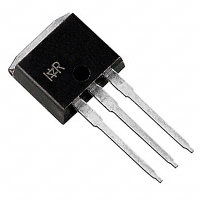
The IRF1104L is an N-Channel MOSFET manufactured by Infineon Technologies, part of the HEXFET® series. This device is rated for 40V drain-to-source voltage with 100A continuous drain current and is housed in a TO-262 package for through-hole mounting applications. The IRF1104L is classified as obsolete, making identification of functionally equivalent substitute parts essential for ongoing design support, production continuity, and system maintenance.
Substiute Parts
Key Parameters
| Parameter | Value | Unit |
|---|---|---|
| Drain to Source Voltage (Vdss) | 40 | V |
| Continuous Drain Current (Id) @ 25°C | 100 | A (Tc) |
| On-State Resistance (Rds On Max) @ 60A, 10V | 9 | mOhm |
| Gate Threshold Voltage (Vgs(th)) @ 250µA | 4 | V |
| Gate Charge (Qg) @ 10V | 93 | nC |
| Input Capacitance (Ciss) @ 25V | 2900 | pF |
| Operating Temperature Range | -55 to 175 | °C (TJ) |
| Package Type | TO-262 | Through Hole |
| Power Dissipation (Max) | 2.4 (Ta), 170 (Tc) | W |
Substitute Part Grouping Explanation
Substitution of the IRF1104L is determined by strict electrical and mechanical compatibility criteria. The following parameters establish the substitution basis:
Primary Electrical Criteria:
- Drain-to-Source Voltage (Vdss): Must equal or exceed 40V
- Continuous Drain Current (Id): Must meet or exceed 100A at 25°C
- Gate Threshold Voltage (Vgs(th)): Must be compatible at 4V nominal
- Maximum Gate Voltage (Vgs Max): Must support ±20V operation
- Operating Temperature Range: Must span -55°C to 175°C
Secondary Electrical Criteria:
- On-State Resistance (Rds On): Lower values indicate improved performance
- Gate Charge (Qg): Lower values reduce switching losses
- Input Capacitance (Ciss): Affects gate drive requirements
Mechanical Criteria:
- Package Type: TO-262 or compatible I2PAK variants
- Mounting Type: Through-hole configuration
- Pin Configuration: TO-262-3 Long Leads compatibility
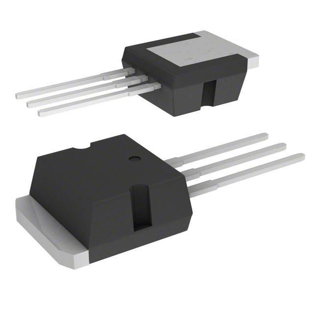
The STI270N4F3 meets all primary and secondary electrical criteria while maintaining mechanical compatibility through the I2PAK package variant, which shares the same pin footprint as TO-262.
Parameter Comparison
| Parameter | IRF1104L (Main Part) | STI270N4F3 (Substitute) | Unit |
|---|---|---|---|
| Manufacturer | Infineon Technologies | STMicroelectronics | — |
| Series | HEXFET® | STripFET™ III | — |
| FET Type | N-Channel | N-Channel | — |
| Drain to Source Voltage (Vdss) | 40 | 40 | V |
| Continuous Drain Current (Id) @ 25°C | 100 | 160 | A (Tc) |
| Rds On (Max) @ 10V | 9 @ 60A | 2.6 @ 80A | mOhm |
| Gate Threshold Voltage (Vgs(th)) @ 250µA | 4 | 4 | V |
| Gate Charge (Qg) @ 10V | 93 | 150 | nC |
| Input Capacitance (Ciss) @ 25V | 2900 | 7400 | pF |
| Vgs (Max) | ±20 | ±20 | V |
| Operating Temperature Range | -55 to 175 | -55 to 175 | °C (TJ) |
| Power Dissipation (Max) | 2.4 (Ta), 170 (Tc) | 330 (Tc) | W |
| Package Type | TO-262 | I2PAK | — |
| Product Status | Obsolete | Obsolete | — |
| RoHS Status | RoHS non-compliant | ROHS3 Compliant | — |
| Automotive Grade | — | AEC-Q101 | — |
Engineering Selection Recommendations
Substitution Feasibility:
The STI270N4F3 is a direct electrical substitute for the IRF1104L based on matching voltage ratings, exceeding current ratings, and identical gate threshold voltage specifications. Both devices operate across the same temperature range and support identical maximum gate voltage levels.
Compliance Considerations:
The IRF1104L is RoHS non-compliant, while the STI270N4F3 is ROHS3 compliant. For new designs or systems requiring regulatory compliance, the STI270N4F3 is the preferred selection. The STI270N4F3 carries AEC-Q101 automotive qualification, providing additional reliability assurance for demanding applications.
Performance Advantages of STI270N4F3:
The substitute part demonstrates superior electrical performance: 60% higher continuous drain current (160A vs. 100A), significantly lower on-state resistance (2.6 mOhm vs. 9 mOhm), and substantially higher power dissipation capability (330W vs. 170W at Tc). These characteristics enable operation at higher current levels with reduced thermal generation.
Package Compatibility:
Both devices use compatible through-hole packages. The IRF1104L uses TO-262, while the STI270N4F3 uses I2PAK. Both package variants share the same TO-262-3 Long Leads pin configuration and footprint, ensuring direct PCB compatibility without layout modifications.
Inventory Status:
The IRF1104L has 888 pieces in stock. The STI270N4F3 has 1585 pieces in stock, providing superior availability for immediate procurement.
Frequently Asked Questions (FAQ)
Q: Can the STI270N4F3 directly replace the IRF1104L in existing circuits?
A: Yes. Both devices share identical voltage ratings (40V Vdss), matching gate threshold voltage (4V), identical maximum gate voltage (±20V), and compatible operating temperature ranges (-55°C to 175°C). The TO-262 and I2PAK packages share the same pin footprint, enabling direct PCB substitution without circuit modifications.
Q: What are the key electrical differences between these parts?
A: The STI270N4F3 provides superior performance in three areas: (1) Continuous drain current is 60% higher (160A vs. 100A), (2) On-state resistance is significantly lower (2.6 mOhm vs. 9 mOhm), and (3) Power dissipation capability is nearly doubled (330W vs. 170W). These differences allow the substitute to handle higher current applications with reduced heat generation.
Q: Are there package considerations for substitution?
A: Both devices use through-hole packages with identical pin configurations (TO-262-3 Long Leads). The IRF1104L uses TO-262 packaging, while the STI270N4F3 uses I2PAK packaging. These variants are mechanically and electrically interchangeable on standard PCB layouts without requiring footprint changes.
Q: What is the significance of the RoHS compliance difference?
A: The IRF1104L is RoHS non-compliant, while the STI270N4F3 is ROHS3 compliant. For applications subject to environmental regulations or customer requirements mandating RoHS compliance, the STI270N4F3 is the appropriate selection. Both devices are REACH unaffected and carry identical ECCN and HTSUS classifications.
Q: Does the higher gate charge of the STI270N4F3 affect circuit design?
A: The STI270N4F3 has higher gate charge (150 nC vs. 93 nC) and input capacitance (7400 pF vs. 2900 pF). These parameters affect gate drive circuit design. Higher values require slightly more gate drive current and energy. Existing gate drive circuits designed for the IRF1104L must be verified to supply adequate drive current for the substitute part, particularly in high-frequency switching applications.
Q: What is the inventory advantage of using the STI270N4F3?
A: The STI270N4F3 has 1585 pieces in stock compared to 888 pieces for the IRF1104L, providing 78% greater availability. This inventory advantage supports production continuity and reduces lead time risk for ongoing manufacturing requirements.
Q: Is the STI270N4F3 suitable for automotive applications?
A: Yes. The STI270N4F3 carries AEC-Q101 automotive qualification, making it suitable for automotive-grade applications. The IRF1104L does not carry automotive qualification. For automotive systems, the STI270N4F3 is the recommended selection.
Alternative Parts

SJ6012L2TP
Littelfuse Inc.
6 Alternative Parts

JMK107BBJ476MA-RE
Taiyo Yuden
10 Alternative Parts

GMK107BBJ475MA-T
Taiyo Yuden
5 Alternative Parts
SJ6020N2ARP
Littelfuse Inc.
3 Alternative Parts
SJ6025R2ATP
Littelfuse Inc.
4 Alternative Parts

2474-05L
API Delevan Inc.
1 Alternative Parts

4590R-684K
API Delevan Inc.
1 Alternative Parts

CM6560R-334
API Delevan Inc.
1 Alternative Parts

CM6460-104
API Delevan Inc.
1 Alternative Parts

5526-12
API Delevan Inc.
1 Alternative Parts