


Request Quote
(Ships tomorrow)
IPW65R420CFDFKSA1 Equivalent & Substitute Parts
Part Overview
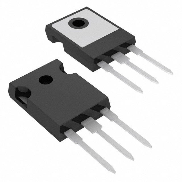
The IPW65R420CFDFKSA1 is an N-Channel 650V 8.7A MOSFET manufactured by Infineon Technologies in the CoolMOS™ series. This device is rated for 83.3W power dissipation and packaged in TO-247-3 through-hole configuration. The part is currently listed as obsolete, making equivalent and substitute parts necessary for ongoing design support and procurement.
Substiute Parts
Key Parameters
| Parameter | Value | Unit |
|---|---|---|
| Drain to Source Voltage (Vdss) | 650 | V |
| Continuous Drain Current (Id) @ 25°C | 8.7 | A (Tc) |
| On-State Resistance (Rds On) @ 3.4A, 10V | 420 | mOhm |
| Gate Threshold Voltage (Vgs(th)) @ 340µA | 4.5 | V |
| Gate Charge (Qg) @ 10V | 32 | nC |
| Input Capacitance (Ciss) @ 100V | 870 | pF |
| Power Dissipation (Max) | 83.3 | W (Tc) |
| Operating Temperature Range | -55 to 150 | °C (TJ) |
| Package Type | TO-247-3 | Through Hole |
| RoHS Status | ROHS3 Compliant | — |
Substitute Part Grouping Explanation
Substitution of the IPW65R420CFDFKSA1 is determined by the following critical parameters:
Direct Equivalent Category:
- Drain to Source Voltage (Vdss): 650V
- Continuous Drain Current (Id): 8.7A
- On-State Resistance (Rds On): 420mOhm @ 10V
- Package Type: TO-247-3
- Operating Temperature: -55°C to 150°C
Higher Voltage Rated Substitutes:
- Drain to Source Voltage (Vdss): 800V (higher rating, backward compatible)
- Continuous Drain Current (Id): ≥8.7A
- On-State Resistance (Rds On): ≤450mOhm @ 10V
- Package Type: TO-247-3 or TO-247 variants
- Operating Temperature: -55°C to 150°C
All substitute parts must maintain N-Channel MOSFET technology, through-hole mounting, and ROHS3 compliance.
Parameter Comparison
| Parameter | IPW65R420CFDFKSA1 | IPW65R420CFDFKSA2 | APT11N80BC3G | IXFH15N80 | SIHG11N80E-GE3 |
|---|---|---|---|---|---|
| Manufacturer | Infineon | Infineon | Microchip | IXYS | Vishay Siliconix |
| Vdss (V) | 650 | 650 | 800 | 800 | 800 |
| Id @ 25°C (A) | 8.7 | 8.7 | 11 | 15 | 12 |
| Rds On @ 10V (mOhm) | 420 | 420 | 450 | 600 | 440 |
| Vgs(th) (V) | 4.5 | 4.5 | 3.9 | 4.5 | 4.0 |
| Qg @ 10V (nC) | 32 | 31.5 | 60 | 200 | 88 |
| Ciss @ Vds (pF) | 870 @ 100V | 870 @ 100V | 1585 @ 25V | 4870 @ 25V | 1670 @ 100V |
| Power Dissipation (W) | 83.3 | 83.3 | 156 | 300 | 179 |
| Operating Temp (°C) | -55 to 150 | -55 to 150 | -55 to 150 | -55 to 150 | -55 to 150 |
| Package | TO-247-3 | TO-247-3 | TO-247-3 | TO-247-3 | TO-247-3 |
| Product Status | Obsolete | Active | Active | Active | Active |
| RoHS Status | ROHS3 Compliant | ROHS3 Compliant | ROHS3 Compliant | ROHS3 Compliant | ROHS3 Compliant |
Engineering Selection Recommendations
Direct Replacement (Recommended First Choice):
IPW65R420CFDFKSA2 is the primary equivalent for IPW65R420CFDFKSA1. Both devices share identical electrical specifications (650V, 8.7A, 420mOhm Rds On) and are from the same manufacturer. The IPW65R420CFDFKSA2 is currently in active production status with 1108 units in stock, making it the optimal choice for direct substitution. The only difference is the packaging variant (Tube vs. original packaging) and a marginal reduction in gate charge (31.5 nC vs. 32 nC), which is within acceptable tolerance.
Higher Voltage Rated Alternatives:
APT11N80BC3G (Microchip Technology), IXFH15N80 (IXYS), and SIHG11N80E-GE3 (Vishay Siliconix) are suitable substitutes when higher voltage rating is acceptable for the application. These parts operate at 800V, providing additional design margin. All three maintain TO-247-3 package compatibility and ROHS3 compliance.
- APT11N80BC3G: 11A continuous current, 450mOhm Rds On, 60 nC gate charge. Suitable for applications requiring moderate current increase.
- IXFH15N80: 15A continuous current, 600mOhm Rds On, 200 nC gate charge. Suitable for higher current applications with increased power dissipation capability (300W).
- SIHG11N80E-GE3: 12A continuous current, 440mOhm Rds On, 88 nC gate charge. Balanced performance between APT11N80BC3G and IXFH15N80.
All substitute parts maintain the -55°C to 150°C operating temperature range and are ROHS3 compliant.
Frequently Asked Questions (FAQ)
Q: Can IPW65R420CFDFKSA2 be used as a direct drop-in replacement for IPW65R420CFDFKSA1?
A: Yes. IPW65R420CFDFKSA2 is electrically and mechanically identical to IPW65R420CFDFKSA1. Both devices have 650V Vdss, 8.7A continuous drain current, and 420mOhm Rds On. The TO-247-3 package is identical. The only difference is packaging format (Tube) and a negligible gate charge reduction (31.5 nC vs. 32 nC).
Q: Why would I choose an 800V rated device over the 650V IPW65R420CFDFKSA2?
A: 800V rated devices (APT11N80BC3G, IXFH15N80, SIHG11N80E-GE3) provide higher voltage margin for applications with transient overvoltage conditions. Selection depends on circuit requirements. If the application operates at or below 650V steady-state, the 650V IPW65R420CFDFKSA2 is preferred due to lower on-state resistance and gate charge.
Q: Are all substitute parts in the same TO-247-3 package?
A: Yes. All listed substitute parts use TO-247-3 or compatible TO-247 package variants (TO-247 [B], TO-247AC, TO-247AD). These are mechanically and thermally compatible with the original IPW65R420CFDFKSA1 footprint.
Q: What is the significance of gate charge (Qg) differences between substitutes?
A: Gate charge affects switching speed and driver circuit requirements. Lower gate charge (IPW65R420CFDFKSA2 at 31.5 nC) requires less driver current and enables faster switching. Higher gate charge devices (IXFH15N80 at 200 nC) may require driver circuit adjustments but offer higher current capability.
Q: Are all substitute parts ROHS3 compliant?
A: Yes. All listed substitute parts are ROHS3 compliant, meeting environmental and regulatory requirements equivalent to the original IPW65R420CFDFKSA1.
Q: What is the difference between Rds On specifications at different current levels?
A: Rds On varies with gate-source voltage (Vgs) and drain current (Id). All listed parts specify Rds On at 10V Vgs. The reference current varies by device design. Lower Rds On at rated current indicates lower conduction losses and reduced heat generation.
Q: Can IXFH15N80 replace IPW65R420CFDFKSA1 in all applications?
A: IXFH15N80 has higher current rating (15A vs. 8.7A) and higher power dissipation (300W vs. 83.3W), making it suitable for higher power applications. However, higher gate charge (200 nC) and input capacitance (4870 pF) may require driver circuit optimization. Verify thermal management and switching frequency compatibility before selection.
Alternative Parts

SJ6012L2TP
Littelfuse Inc.
6 Alternative Parts

JMK107BBJ476MA-RE
Taiyo Yuden
10 Alternative Parts

GMK107BBJ475MA-T
Taiyo Yuden
5 Alternative Parts
SJ6020N2ARP
Littelfuse Inc.
3 Alternative Parts
SJ6025R2ATP
Littelfuse Inc.
4 Alternative Parts

2474-05L
API Delevan Inc.
1 Alternative Parts

4590R-684K
API Delevan Inc.
1 Alternative Parts

CM6560R-334
API Delevan Inc.
1 Alternative Parts

CM6460-104
API Delevan Inc.
1 Alternative Parts

5526-12
API Delevan Inc.
1 Alternative Parts