


Request Quote
(Ships tomorrow)
IPP048N06L G N-Channel 60V 100A MOSFET Equivalent & Substitute Parts
Part Overview
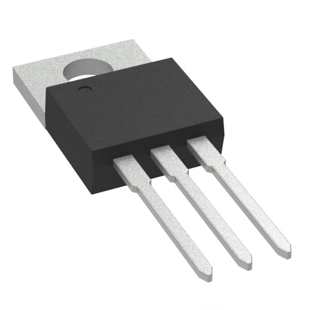
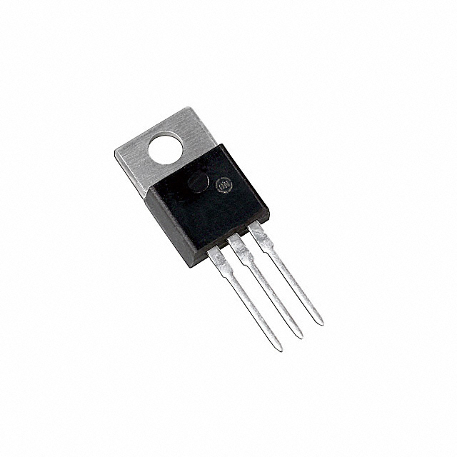
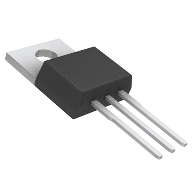
The IPP048N06L G is an N-Channel 60V 100A MOSFET manufactured by Infineon Technologies in the OptiMOS™ series. This device is rated for 300W power dissipation and features a TO-220-3 through-hole package. The part is currently classified as obsolete, making identification of functionally equivalent substitute components essential for ongoing design support, production continuity, and system maintenance.
Substitute parts must maintain electrical compatibility across drain-source voltage, continuous drain current, on-resistance characteristics, and thermal performance parameters while accommodating the through-hole TO-220-3 package format.
Substiute Parts
Key Parameters
| Parameter | Value | Unit | Specification Condition |
|---|---|---|---|
| Drain to Source Voltage (Vdss) | 60 | V | Maximum rating |
| Continuous Drain Current (Id) | 100 | A | @ 25°C (Tc) |
| On-Resistance (Rds On Max) | 4.7 | mOhm | @ 100A, 10V Vgs |
| Gate Threshold Voltage (Vgs th Max) | 2 | V | @ 270µA Id |
| Gate Charge (Qg Max) | 225 | nC | @ 10V Vgs |
| Power Dissipation (Max) | 300 | W | @ Tc |
| Operating Temperature Range | -55 to 175 | °C | Tj |
| Package Type | TO-220-3 | — | Through-hole |
| Technology | MOSFET (Metal Oxide) | — | N-Channel |
Substitute Part Grouping Explanation
Substitute parts are grouped based on strict electrical and mechanical compatibility criteria derived from the IPP048N06L G specifications:
Primary Substitution Criteria:
- Drain-Source Voltage (Vdss): 60V minimum (allows higher voltage ratings)
- Continuous Drain Current (Id): 100A minimum @ 25°C
- On-Resistance (Rds On): ≤4.7 mOhm @ rated current and 10V Vgs
- Package: TO-220-3 through-hole configuration
- Technology: N-Channel MOSFET
- Operating Temperature: -55°C to 175°C minimum
Grouping Logic:
Group 1 – Direct Electrical Equivalents (60V, 100A class): Parts meeting or exceeding the 60V/100A rating with comparable on-resistance and gate charge characteristics. These provide the closest functional replacement with minimal circuit redesign.
Group 2 – Voltage-Rated Alternatives (75V–100V, 75A–80A class): Parts with higher voltage ratings (75V–100V) but reduced continuous current (75A–80A). These are suitable for applications where voltage margin is prioritized or where actual operating current is below 100A.
Group 3 – Lower Current Alternatives (60V–80V, 14A–18A Ta / 80A Tc class): Parts with reduced ambient temperature current ratings but maintained case temperature ratings. These are applicable in thermally managed designs where continuous current at 25°C ambient is not the limiting factor.
All substitute parts maintain the TO-220-3 package, N-Channel MOSFET technology, and -55°C to 175°C operating temperature range.
Parameter Comparison
| Manufacturer Part Number | Manufacturer | Vdss (V) | Id @ 25°C (A) | Rds On Max (mOhm) | Vgs th Max (V) | Qg Max (nC) | Power Diss. (W) | Product Status | Package |
|---|---|---|---|---|---|---|---|---|---|
| IPP048N06L G | Infineon | 60 | 100 (Tc) | 4.7 @ 100A, 10V | 2 @ 270µA | 225 @ 10V | 300 | Obsolete | TO-220-3 |
| CSD18532KCS | Texas Instruments | 60 | 100 (Tc) | 4.2 @ 100A, 10V | 2.2 @ 250µA | 53 @ 10V | 250 | Active | TO-220-3 |
| FDP038AN06A0-F102 | onsemi | 60 | 80 (Tc) | 3.8 @ 80A, 10V | 4 @ 250µA | 124 @ 10V | 310 | Active | TO-220-3 |
| FDP050AN06A0 | onsemi | 60 | 80 (Tc) | 5 @ 80A, 10V | 4 @ 250µA | 80 @ 10V | 245 | Active | TO-220-3 |
| FDP5800 | onsemi | 60 | 80 (Tc) | 6 @ 80A, 10V | 2.5 @ 250µA | 145 @ 10V | 242 | Active | TO-220-3 |
| PSMN005-75P,127 | Nexperia USA Inc. | 75 | 75 (Tc) | 5 @ 25A, 10V | 4 @ 1mA | 165 @ 10V | 230 | Active | TO-220-3 |
| PSMN016-100PS,127 | Nexperia USA Inc. | 100 | 57 (Tj) | 16 @ 15A, 10V | 4 @ 1mA | 49 @ 10V | 148 | Obsolete | TO-220-3 |
| PSMN3R0-60PS,127 | Nexperia USA Inc. | 60 | 100 (Tc) | 3 @ 25A, 10V | 4 @ 1mA | 130 @ 10V | 306 | Obsolete | TO-220-3 |
| PSMN4R4-80PS,127 | Nexperia USA Inc. | 80 | 100 (Tc) | 4.1 @ 15A, 10V | 4 @ 1mA | 125 @ 10V | 306 | Obsolete | TO-220-3 |
| PSMN4R6-60PS,127 | Nexperia USA Inc. | 60 | 100 (Tc) | 4.6 @ 25A, 10V | 4 @ 1mA | 70.8 @ 10V | 211 | Obsolete | TO-220-3 |
| PSMN5R0-80PS,127 | Nexperia USA Inc. | 80 | 100 (Tc) | 4.7 @ 15A, 10V | 4 @ 1mA | 101 @ 10V | 270 | Obsolete | TO-220-3 |
Engineering Selection Recommendations
Active Product Preference: CSD18532KCS (Texas Instruments NexFET™ series) is the primary recommended substitute. This part is in active production status with ROHS3 compliance certification. It matches the IPP048N06L G electrical specifications (60V, 100A Tc) with superior on-resistance (4.2 mOhm vs. 4.7 mOhm) and significantly lower gate charge (53 nC vs. 225 nC), reducing switching losses. Power dissipation is rated at 250W versus 300W, requiring thermal design verification for high-power applications.
Secondary Active Alternatives: onsemi FDP038AN06A0-F102 and FDP050AN06A0 (PowerTrench® series) are active production alternatives with 60V ratings. Both are ROHS3 compliant. FDP038AN06A0-F102 delivers 80A continuous current with lower on-resistance (3.8 mOhm) and higher power dissipation (310W). FDP050AN06A0 provides 80A continuous current with 5 mOhm on-resistance and 245W power dissipation. These are suitable for applications where continuous current requirement is ≤80A.
onsemi FDP5800 (PowerTrench® series) is an active alternative rated 60V, 80A (Tc) with 6 mOhm on-resistance and 242W power dissipation. ROHS3 compliant.
Voltage-Rated Alternatives: Nexperia PSMN005-75P,127 (TrenchMOS™ series) is active production with 75V rating and 75A continuous current. On-resistance is 5 mOhm @ 25A, 10V. This part is suitable for designs requiring voltage margin above 60V where continuous current is ≤75A.
Obsolete Parts Not Recommended for New Designs: PSMN016-100PS,127, PSMN3R0-60PS,127, PSMN4R4-80PS,127, PSMN4R6-60PS,127, and PSMN5R0-80PS,127 are classified as obsolete. While inventory is available, these parts should not be selected for new product designs. They may be used only for legacy system maintenance where supply chain continuity is established.
Compliance Considerations: All active substitute parts carry ROHS3 compliance and REACH Unaffected status, matching the regulatory profile of the IPP048N06L G. Thermal design verification is required when substituting parts with lower power dissipation ratings (250W vs. 300W).
Frequently Asked Questions (FAQ)
Q1: Can CSD18532KCS directly replace IPP048N06L G in existing PCB layouts?
A: Yes. Both parts use the TO-220-3 through-hole package with identical pinout (Gate, Drain, Source). No PCB modification is required. However, thermal management should be reviewed because CSD18532KCS is rated 250W versus 300W for the original part. If the original design operated near thermal limits, additional heatsinking or airflow may be necessary.
Q2: What is the primary difference between Group 1 (60V, 100A) and Group 2 (75V–100V, 75A–80A) substitutes?
A: Group 1 substitutes maintain the 100A continuous current rating at 25°C case temperature, providing direct current capacity replacement. Group 2 substitutes have higher voltage ratings (75V or 100V) but reduced continuous current (75A or 80A). Group 2 is appropriate only when the application's actual operating current is ≤75A or ≤80A, or when higher voltage margin is a design requirement.
Q3: Why is gate charge (Qg) important when selecting a substitute?
A: Gate charge determines the energy required to switch the MOSFET on and off. CSD18532KCS has significantly lower gate charge (53 nC vs. 225 nC), reducing switching losses and allowing faster switching frequencies. However, gate driver circuits must be verified to ensure they can supply the required gate current within the specified switching time. Lower gate charge may require gate driver adjustment.
Q4: Can I use FDP038AN06A0-F102 (80A) in place of IPP048N06L G (100A)?
A: FDP038AN06A0-F102 is suitable only if the application's continuous drain current requirement is ≤80A at 25°C case temperature. If the design requires 100A continuous current, this part will exceed its current rating. Verify actual operating current in the application before substitution.
Q5: Are obsolete parts (PSMN series) acceptable for production use?
A: Obsolete parts should not be used in new product designs. They may be used only for maintenance and repair of existing systems where supply chain continuity has been established with the component distributor. For new designs, select from active production parts: CSD18532KCS, FDP038AN06A0-F102, FDP050AN06A0, FDP5800, or PSMN005-75P,127.
Q6: What thermal considerations apply when substituting to CSD18532KCS?
A: CSD18532KCS is rated 250W maximum power dissipation versus 300W for IPP048N06L G. In applications operating near thermal limits, verify that the heatsink thermal resistance and ambient temperature conditions remain within acceptable limits. Calculate junction temperature using: Tj = Ta + (Pd × Rth(j-a)), where Pd is actual power dissipation and Rth(j-a) is junction-to-ambient thermal resistance. Ensure Tj remains below 175°C maximum.
Q7: Do all substitute parts have the same gate threshold voltage (Vgs th)?
A: No. IPP048N06L G has Vgs th Max of 2V @ 270µA, while most Nexperia substitutes specify 4V @ 1mA. CSD18532KCS specifies 2.2V @ 250µA. Higher threshold voltages may affect gate driver circuit design, particularly for low-voltage gate drive applications. Verify gate driver output voltage compatibility with the selected substitute's threshold specification.
Q8: Which substitute offers the best on-resistance performance?
A: PSMN3R0-60PS,127 (obsolete) offers 3 mOhm on-resistance, the lowest among all listed parts. Among active production parts, CSD18532KCS provides 4.2 mOhm and FDP038AN06A0-F102 provides 3.8 mOhm. Lower on-resistance reduces conduction losses and heat generation. However, obsolete parts should not be selected for new designs.
Q9: What is the difference between Tc (case temperature) and Tj (junction temperature) current ratings?
A: Tc (case temperature) ratings assume the case is maintained at 25°C through external cooling. Tj (junction temperature) ratings are measured at the actual junction temperature. Most modern parts specify Tc ratings. When comparing parts, ensure you are comparing equivalent temperature conditions. IPP048N06L G specifies 100A @ Tc (case temperature).
Q10: Can I use PSMN005-75P,127 (75V) in a 60V application?
A: Yes. PSMN005-75P,127 has a higher voltage rating (75V) than required (60V), providing voltage margin. However, it is rated for only 75A continuous current versus 100A for the original part. Use this substitute only if the application's continuous current requirement is ≤75A. The higher voltage rating does not degrade performance in a 60V application.
Alternative Parts

SJ6012L2TP
Littelfuse Inc.
6 Alternative Parts

JMK107BBJ476MA-RE
Taiyo Yuden
10 Alternative Parts

GMK107BBJ475MA-T
Taiyo Yuden
5 Alternative Parts
SJ6020N2ARP
Littelfuse Inc.
3 Alternative Parts
SJ6025R2ATP
Littelfuse Inc.
4 Alternative Parts

2474-05L
API Delevan Inc.
1 Alternative Parts

4590R-684K
API Delevan Inc.
1 Alternative Parts

CM6560R-334
API Delevan Inc.
1 Alternative Parts

CM6460-104
API Delevan Inc.
1 Alternative Parts

5526-12
API Delevan Inc.
1 Alternative Parts