


Request Quote
(Ships tomorrow)
IPI65R150CFDXKSA1 Equivalent & Substitute Parts
Part Overview
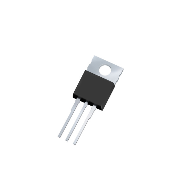
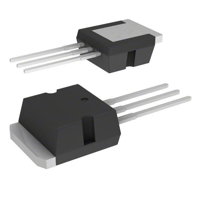
The IPI65R150CFDXKSA1 is an N-Channel 650V 22.4A MOSFET manufactured by Infineon Technologies in the CoolMOS™ series. This device is packaged in TO-262-3 (I2PAK) configuration and rated for 195.3W power dissipation at case temperature. The part is classified as obsolete, necessitating identification of active equivalent and substitute components for new designs and ongoing production requirements. Substitute parts must maintain functional compatibility within the electrical and mechanical constraints of the original application.
Substiute Parts
Key Parameters
| Parameter | Value | Unit |
|---|---|---|
| Drain to Source Voltage (Vdss) | 650 | V |
| Continuous Drain Current (Id) @ 25°C | 22.4 | A |
| On-State Resistance (Rds On) @ 10V | 150 | mOhm |
| Gate Charge (Qg) @ 10V | 86 | nC |
| Power Dissipation (Max) | 195.3 | W |
| Operating Temperature Range | -55 to 150 | °C |
| Package Type | TO-262-3 (I2PAK) | — |
| Mounting Type | Through Hole | — |
| Gate Voltage (Vgs) Max | ±20 | V |
Substitute Part Grouping Explanation
Substitution eligibility is determined by the following criteria:
Primary Compatibility Parameters:
- Drain to Source Voltage (Vdss): Substitute must equal or exceed 650V
- Continuous Drain Current (Id): Substitute must equal or exceed 22.4A at 25°C
- Package Type: Substitute must be compatible with TO-262-3 (I2PAK) through-hole mounting
- Operating Temperature Range: Substitute must support -55°C to 150°C
- Gate Voltage Rating (Vgs): Substitute must support ±20V minimum
Secondary Electrical Parameters:
- On-State Resistance (Rds On): Lower values indicate improved performance
- Gate Charge (Qg): Lower values indicate faster switching characteristics
- Power Dissipation: Substitute must support minimum 195.3W at case temperature
The substitute parts listed below are grouped by their ability to meet these criteria within the constraints of active product availability and manufacturing compliance standards.
Parameter Comparison
| Parameter | IPI65R150CFDXKSA1 | STI20N65M5 | STI24NM60N | STI33N60M2 | IPP60R145CFD7XKSA1 |
|---|---|---|---|---|---|
| Manufacturer | Infineon | STMicroelectronics | STMicroelectronics | STMicroelectronics | Infineon |
| Vdss (V) | 650 | 650 | 600 | 600 | 600 |
| Id @ 25°C (A) | 22.4 | 18 | 17 | 26 | 16 |
| Rds On @ 10V (mOhm) | 150 | 190 | 190 | 125 | 145 |
| Qg @ 10V (nC) | 86 | 36 | 46 | 45.5 | 31 |
| Power Dissipation (W) | 195.3 | 130 | 125 | 190 | 83 |
| Package | TO-262-3 | TO-262 (I2PAK) | I2PAK | TO-262 (I2PAK) | TO-220-3 |
| Vgs Max (V) | ±20 | ±25 | ±30 | ±25 | ±20 |
| Operating Temp (°C) | -55 to 150 | -55 to 150 | -55 to 150 | -55 to 150 | -55 to 150 |
| Product Status | Obsolete | Active | Active | Active | Active |
| RoHS Status | — | ROHS3 Compliant | ROHS3 Compliant | ROHS3 Compliant | ROHS3 Compliant |
Engineering Selection Recommendations
STI20N65M5 (STMicroelectronics MDmesh™ V)
This substitute maintains the 650V Vdss rating matching the original part specification. The 18A continuous drain current falls below the original 22.4A rating, requiring thermal and current distribution analysis for applications operating at maximum current levels. The device is active and ROHS3 compliant. Package compatibility is confirmed with TO-262 (I2PAK) through-hole mounting. Gate charge of 36nC provides improved switching performance compared to the original 86nC specification.
STI33N60M2 (STMicroelectronics MDmesh™ II Plus)
This substitute provides the highest continuous drain current at 26A, exceeding the original 22.4A specification. The Vdss rating is reduced to 600V, which is acceptable for applications not requiring the full 650V margin. Power dissipation capability of 190W closely matches the original 195.3W specification. The device is active and ROHS3 compliant. Package compatibility is confirmed with TO-262 (I2PAK) through-hole mounting. On-state resistance of 125mOhm is superior to the original 150mOhm.
STI24NM60N (STMicroelectronics MDmesh™ II)
This substitute provides 17A continuous drain current with 600V Vdss rating. Power dissipation of 125W is lower than the original specification. The device is active and ROHS3 compliant. Package compatibility is confirmed with I2PAK through-hole mounting. Gate voltage rating of ±30V exceeds the original ±20V specification, providing additional design margin.
IPP60R145CFD7XKSA1 (Infineon CoolMOS™ CFD7)
This substitute is from the same manufacturer as the original part, maintaining design continuity within the Infineon CoolMOS™ product family. The 600V Vdss rating is reduced from the original 650V. Continuous drain current of 16A falls below the original 22.4A specification. Power dissipation of 83W is significantly lower than the original 195.3W. Package configuration is TO-220-3, which differs from the original TO-262-3 (I2PAK) and requires PCB layout modification. The device is active and ROHS3 compliant.
Frequently Asked Questions (FAQ)
Q: Can STI20N65M5 be used as a direct replacement for IPI65R150CFDXKSA1?
A: STI20N65M5 maintains the 650V Vdss rating and TO-262 (I2PAK) package compatibility. However, the continuous drain current is reduced from 22.4A to 18A. Direct substitution is permissible only in applications where the maximum drain current does not exceed 18A at 25°C case temperature.
Q: What is the primary advantage of STI33N60M2 over the original part?
A: STI33N60M2 provides superior continuous drain current at 26A and lower on-state resistance at 125mOhm compared to the original 150mOhm. These characteristics result in reduced power dissipation in high-current applications. The trade-off is a reduced Vdss rating of 600V versus the original 650V.
Q: Why is IPP60R145CFD7XKSA1 listed as a substitute if it uses a different package?
A: IPP60R145CFD7XKSA1 is included as a substitute option for applications where PCB layout modification is feasible. The TO-220-3 package requires different mounting and thermal management considerations compared to the original TO-262-3 (I2PAK) configuration. This substitute is suitable only when design flexibility permits package change.
Q: Are all substitute parts ROHS3 compliant?
A: Yes. All listed substitute parts carry ROHS3 compliance certification. The original IPI65R150CFDXKSA1 does not specify RoHS status in the provided data.
Q: What is the significance of gate charge (Qg) differences between parts?
A: Gate charge affects switching speed and driver circuit requirements. Lower gate charge values, such as those in STI20N65M5 (36nC) and IPP60R145CFD7XKSA1 (31nC), enable faster switching transitions compared to the original part (86nC). This may require driver circuit evaluation to ensure compatibility.
Q: Can multiple substitute parts be used interchangeably in the same application?
A: No. Each substitute part has distinct electrical characteristics. Selection must be based on specific application requirements for voltage, current, power dissipation, and thermal management. Interchangeability is not guaranteed without detailed circuit analysis.
Q: What is the impact of reduced Vdss rating in STI24NM60N and STI33N60M2?
A: The reduction from 650V to 600V Vdss is acceptable for applications with maximum operating voltages below 600V. Applications requiring the full 650V margin must use STI20N65M5 or equivalent 650V-rated devices.
Q: Are there inventory considerations for substitute selection?
A: Yes. STI24NM60N has the highest inventory availability at 7400 pieces. STI33N60M2 has 2200 pieces, STI20N65M5 has 2126 pieces, and IPP60R145CFD7XKSA1 has 750 pieces. Inventory levels may influence long-term supply chain planning.
Alternative Parts

SJ6012L2TP
Littelfuse Inc.
6 Alternative Parts

JMK107BBJ476MA-RE
Taiyo Yuden
10 Alternative Parts

GMK107BBJ475MA-T
Taiyo Yuden
5 Alternative Parts
SJ6020N2ARP
Littelfuse Inc.
3 Alternative Parts
SJ6025R2ATP
Littelfuse Inc.
4 Alternative Parts

2474-05L
API Delevan Inc.
1 Alternative Parts

4590R-684K
API Delevan Inc.
1 Alternative Parts

CM6560R-334
API Delevan Inc.
1 Alternative Parts

CM6460-104
API Delevan Inc.
1 Alternative Parts

5526-12
API Delevan Inc.
1 Alternative Parts