


Request Quote
(Ships tomorrow)
IPD65R420CFDATMA2 Equivalent & Substitute Parts
Part Overview
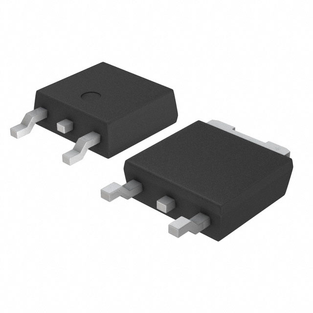
The IPD65R420CFDATMA2 is an N-Channel 650V 8.7A MOSFET manufactured by Infineon Technologies in the CoolMOS™ CFD2 series. This surface mount device is packaged in TO-252-3 (DPAK) configuration and is designed for high-voltage switching applications requiring 650V drain-to-source voltage capability. The part is Active status and RoHS3 compliant. Equivalent and substitute parts are identified based on matching or exceeding critical electrical parameters including drain-to-source voltage rating, continuous drain current, on-resistance characteristics, and compatible packaging standards.
Substiute Parts
Key Parameters
| Parameter | Value | Unit |
|---|---|---|
| Drain to Source Voltage (Vdss) | 650 | V |
| Continuous Drain Current (Id) @ 25°C | 8.7 | A |
| Rds On (Max) @ 3.4A, 10V | 420 | mOhm |
| Gate Charge (Qg) @ 10V | 31.5 | nC |
| Power Dissipation (Max) | 83.3 | W |
| Operating Temperature Range | -55 to 150 | °C |
| Package Type | TO-252-3 DPAK | - |
| Mounting Type | Surface Mount | - |
Substitute Part Grouping Explanation
Substitution eligibility for the IPD65R420CFDATMA2 is determined by the following critical parameters:
Voltage Rating Requirement: Substitute parts must have a Vdss rating equal to or greater than 650V. This ensures the device can withstand the same or higher voltage stress in the application circuit.
Current Rating Requirement: Substitute parts must have a continuous drain current (Id) rating equal to or greater than 8.7A at 25°C. This ensures adequate current-carrying capacity for the intended application.
On-Resistance (Rds On) Requirement: Substitute parts must have Rds On values compatible with the application's thermal and efficiency requirements. Lower Rds On values indicate better performance characteristics.
Package Compatibility: All substitute parts must use TO-252-3 DPAK surface mount packaging to ensure mechanical and electrical compatibility with existing PCB layouts.
Operating Temperature Range: Substitute parts must support the full operating temperature range of -55°C to 150°C.
Compliance Status: All substitute parts must maintain RoHS3 compliance and equivalent regulatory certifications.
The three identified substitute parts meet these criteria with the following characteristics:
- STD11NM65N: Matches 650V voltage rating, exceeds current rating (11A vs 8.7A), compatible DPAK package
- TK560P65Y,RQ: Matches 650V voltage rating, lower current rating (7A vs 8.7A), compatible DPAK package
- SIHD7N60E-GE3: Lower voltage rating (600V vs 650V), lower current rating (7A vs 8.7A), compatible DPAK package
Parameter Comparison
| Parameter | IPD65R420CFDATMA2 | STD11NM65N | TK560P65Y,RQ | SIHD7N60E-GE3 |
|---|---|---|---|---|
| Manufacturer | Infineon Technologies | STMicroelectronics | Toshiba Semiconductor | Vishay Siliconix |
| Vdss (V) | 650 | 650 | 650 | 600 |
| Id @ 25°C (A) | 8.7 | 11 | 7 | 7 |
| Rds On (Max) @ 10V (mOhm) | 420 | 455 | 560 | 600 |
| Gate Charge @ 10V (nC) | 31.5 | 29 | 14.5 | 40 |
| Power Dissipation (Max) (W) | 83.3 | 110 | 60 | 78 |
| Operating Temperature (°C) | -55 to 150 | -55 to 150 | -55 to 150 | -55 to 150 |
| Package | TO-252-3 DPAK | TO-252-3 DPAK | TO-252-3 DPAK | TO-252-3 DPAK |
| Mounting Type | Surface Mount | Surface Mount | Surface Mount | Surface Mount |
| RoHS Status | ROHS3 Compliant | ROHS3 Compliant | ROHS3 Compliant | Not specified |
| Product Status | Active | Active | Active | Active |
Engineering Selection Recommendations
Primary Substitute: STD11NM65N
The STD11NM65N from STMicroelectronics is the most direct substitute for the IPD65R420CFDATMA2. It maintains the identical 650V voltage rating and exceeds the continuous drain current specification (11A vs 8.7A). The on-resistance of 455mOhm is marginally higher than the original part's 420mOhm, representing a 8.3% increase. This device is RoHS3 compliant, Active status, and packaged in compatible TO-252-3 DPAK format. The higher current rating provides additional design margin for thermal management.
Secondary Substitute: TK560P65Y,RQ
The TK560P65Y,RQ from Toshiba Semiconductor maintains the 650V voltage rating required for the application. However, the continuous drain current is reduced to 7A, which is 19.5% lower than the original specification. The on-resistance increases to 560mOhm, representing a 33.3% increase over the original part. This device is suitable only for applications where the reduced current rating does not compromise circuit performance. The device is RoHS3 compliant, Active status, and uses compatible TO-252-3 DPAK packaging. The lower gate charge (14.5nC) may provide switching speed advantages in certain circuit topologies.
Tertiary Substitute: SIHD7N60E-GE3
The SIHD7N60E-GE3 from Vishay Siliconix has a reduced voltage rating of 600V, which is 7.7% lower than the required 650V specification. The continuous drain current is 7A, representing a 19.5% reduction from the original part. The on-resistance is 600mOhm, a 42.9% increase over the original specification. This device is suitable only for applications where the voltage stress does not exceed 600V and where the reduced current and increased on-resistance are acceptable. The device is Active status and uses compatible TO-252-3 DPAK packaging. RoHS3 compliance status is not specified in the provided data.
All substitute parts maintain surface mount DPAK packaging compatibility and the full -55°C to 150°C operating temperature range.
Frequently Asked Questions (FAQ)
Q: Can the STD11NM65N be used as a direct replacement for the IPD65R420CFDATMA2?
A: The STD11NM65N is electrically compatible as a substitute. It maintains the 650V voltage rating and exceeds the current specification. The slightly higher on-resistance (455mOhm vs 420mOhm) results in marginally higher power dissipation but remains within acceptable thermal limits for most applications. Both devices use identical TO-252-3 DPAK packaging and support the same operating temperature range.
Q: What are the limitations of using the TK560P65Y,RQ as a substitute?
A: The TK560P65Y,RQ has a reduced continuous drain current rating of 7A compared to the original 8.7A specification. This 19.5% reduction may limit its use in high-current applications. The on-resistance is also higher at 560mOhm. The voltage rating of 650V matches the original part. Selection of this device should be based on verification that the application's actual current requirements do not exceed 7A.
Q: Why is the SIHD7N60E-GE3 listed as a substitute if it has a lower voltage rating?
A: The SIHD7N60E-GE3 is included as a tertiary option for applications where the actual voltage stress does not exceed 600V. While the 650V rating of the original part provides design margin, some circuit topologies may operate safely at 600V. This device should be selected only after confirming that the application's maximum voltage stress remains below 600V. The reduced current rating (7A) and increased on-resistance (600mOhm) also require verification against application requirements.
Q: Are all substitute parts RoHS3 compliant?
A: The STD11NM65N and TK560P65Y,RQ are explicitly RoHS3 compliant. The SIHD7N60E-GE3 RoHS3 compliance status is not specified in the provided technical data. Verification of compliance status should be obtained from the manufacturer if RoHS3 certification is required for the application.
Q: Do all substitute parts use the same package as the original IPD65R420CFDATMA2?
A: Yes. All three substitute parts use the TO-252-3 DPAK surface mount package, ensuring mechanical and electrical compatibility with existing PCB layouts designed for the IPD65R420CFDATMA2.
Q: What is the significance of the gate charge differences between these devices?
A: Gate charge (Qg) affects switching speed and driver circuit requirements. The original IPD65R420CFDATMA2 has a gate charge of 31.5nC. The STD11NM65N (29nC) and TK560P65Y,RQ (14.5nC) have lower gate charges, potentially enabling faster switching. The SIHD7N60E-GE3 (40nC) has higher gate charge, requiring more driver current. These differences should be evaluated in the context of the specific gate driver circuit used in the application.
Q: How do the power dissipation ratings compare?
A: The original IPD65R420CFDATMA2 has a maximum power dissipation of 83.3W. The STD11NM65N (110W) exceeds this rating, providing additional thermal margin. The TK560P65Y,RQ (60W) and SIHD7N60E-GE3 (78W) are lower, which may require more careful thermal management depending on the application's duty cycle and heat dissipation design.
Alternative Parts

SJ6012L2TP
Littelfuse Inc.
6 Alternative Parts

JMK107BBJ476MA-RE
Taiyo Yuden
10 Alternative Parts

GMK107BBJ475MA-T
Taiyo Yuden
5 Alternative Parts
SJ6020N2ARP
Littelfuse Inc.
3 Alternative Parts
SJ6025R2ATP
Littelfuse Inc.
4 Alternative Parts

2474-05L
API Delevan Inc.
1 Alternative Parts

4590R-684K
API Delevan Inc.
1 Alternative Parts

CM6560R-334
API Delevan Inc.
1 Alternative Parts

CM6460-104
API Delevan Inc.
1 Alternative Parts

5526-12
API Delevan Inc.
1 Alternative Parts