


Request Quote
(Ships tomorrow)
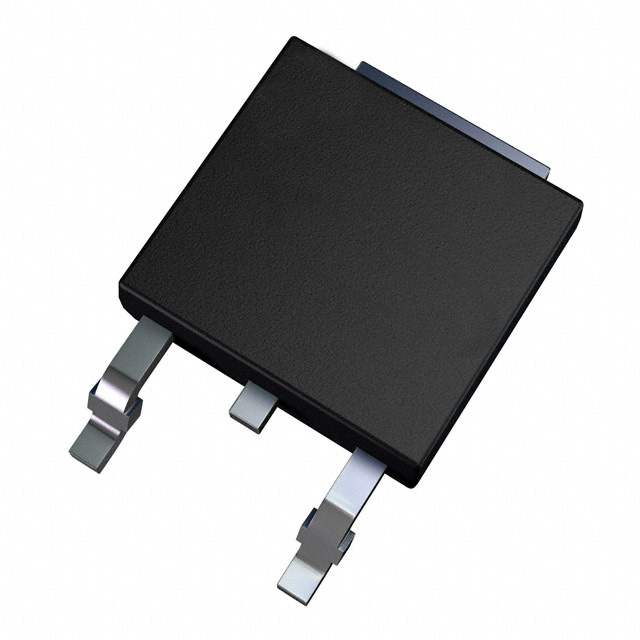
IPD65R420CFDAATMA1 N-Channel 650V 8.7A MOSFET Equivalent & Substitute Parts
Part Overview
The IPD65R420CFDAATMA1 is an N-Channel 650V 8.7A surface mount MOSFET manufactured by Infineon Technologies, part of the CoolMOS™ series. This device operates in the TO-252-3 (DPAK) package and is qualified to AEC-Q101 automotive standards with Active product status. Substitute parts are identified when original inventory is unavailable, when design flexibility is required across manufacturing sources, or when equivalent electrical and mechanical specifications can satisfy application requirements within the defined parameter tolerances.
Substiute Parts
Key Parameters
| Parameter | Value | Unit |
|---|---|---|
| Drain to Source Voltage (Vdss) | 650 | V |
| Continuous Drain Current (Id) @ 25°C | 8.7 | A |
| On-State Resistance (Rds On) @ 3.4A, 10V | 420 | mOhm |
| Gate Threshold Voltage (Vgs(th)) @ 345µA | 4.5 | V |
| Gate Charge (Qg) @ 10V | 32 | nC |
| Power Dissipation (Max) | 83.3 | W |
| Operating Temperature Range | -40 to 150 | °C |
| Package Type | TO-252-3 (DPAK) | — |
| Mounting Type | Surface Mount | — |
| RoHS Status | ROHS3 Compliant | — |
| AEC-Q101 Qualification | Yes | — |
Substitute Part Grouping Explanation
Substitution of the IPD65R420CFDAATMA1 is determined by strict alignment of the following electrical and mechanical parameters:
Primary Substitution Criteria:
- Drain to Source Voltage (Vdss): 600V minimum to 700V maximum
- Continuous Drain Current (Id): 7A minimum to 11A maximum
- On-State Resistance (Rds On): 420mOhm to 600mOhm range
- Package Type: TO-252-3 (DPAK) surface mount only
- Gate Drive Voltage: 10V standard
- Operating Temperature: -40°C to 150°C minimum range
Substitution Logic: Parts are grouped as equivalent when they maintain voltage and current ratings within ±10% of the main part specifications, operate within the same temperature envelope, and use identical package geometry. Parts with higher Vdss ratings (600V to 700V) are acceptable as they provide voltage margin. Parts with current ratings between 7A and 11A are acceptable as they cover the 8.7A requirement. On-state resistance values between 420mOhm and 600mOhm are acceptable within the switching loss and thermal design parameters of typical applications.
Parameter Comparison
| Part Number | Manufacturer | Vdss (V) | Id @ 25°C (A) | Rds On (mOhm) | Qg @ 10V (nC) | Power Diss. (W) | Temp Range (°C) | Package | Status |
|---|---|---|---|---|---|---|---|---|---|
| IPD65R420CFDAATMA1 | Infineon | 650 | 8.7 | 420 | 32 | 83.3 | -40 to 150 | TO-252-3 | Active |
| STD8N65M5 | STMicroelectronics | 650 | 7 | 600 | 15 | 70 | -55 to 150 | TO-252-3 | Active |
| STD10N60M2 | STMicroelectronics | 600 | 7.5 | 600 | 13.5 | 85 | -55 to 150 | TO-252-3 | Active |
| AOD7S60 | Alpha & Omega Semiconductor | 600 | 7 | 600 | 8.2 | 83 | -55 to 150 | TO-252-3 | Not For New Designs |
| STD11NM65N | STMicroelectronics | 650 | 11 | 455 | 29 | 110 | -55 to 150 | TO-252-3 | Active |
| IXTY8N70X2 | IXYS | 700 | 8 | 500 | 12 | 150 | -55 to 150 | TO-252-3 | Active |
| STD11NM60ND | STMicroelectronics | 600 | 10 | 450 | 30 | 90 | -55 to 150 | TO-252-3 | Active |
| TK8P60W5,RVQ | Toshiba Semiconductor | 600 | 8 | 560 | 22 | 80 | -55 to 150 | TO-252-3 | Active |
Engineering Selection Recommendations
Primary Recommendation: STD11NM65N The STD11NM65N from STMicroelectronics maintains the 650V Vdss rating of the original IPD65R420CFDAATMA1, ensuring voltage compatibility in high-voltage switching applications. With 11A continuous drain current and 455mOhm on-state resistance, this part operates within acceptable electrical parameters. Active product status and AEC-Q101 compliance path through STMicroelectronics' automotive qualification ensure long-term availability and design support.
Secondary Recommendation: STD10N60M2 The STD10N60M2 provides a 600V Vdss rating with 7.5A continuous current and 600mOhm on-state resistance. This part is suitable for applications where 50V voltage margin reduction is acceptable. High inventory availability (28,109 pcs) and Active status support supply chain continuity. The MDmesh™ II Plus technology series ensures performance consistency.
Alternative for High-Current Applications: STD11NM60ND The STD11NM60ND offers 10A continuous drain current at 600V with 450mOhm on-state resistance, providing improved current handling and lower switching losses. This part is appropriate when thermal design permits higher power dissipation (90W) and 50V voltage margin reduction is acceptable.
Voltage-Margin Alternative: IXTY8N70X2 The IXTY8N70X2 from IXYS provides 700V Vdss with 8A continuous current, offering additional voltage headroom for high-voltage transient protection. Active product status and 150W power dissipation rating support demanding thermal environments. This part is suitable when circuit design benefits from increased voltage margin.
Not Recommended for New Designs: AOD7S60 The AOD7S60 from Alpha & Omega Semiconductor meets electrical parameter requirements but carries "Not For New Designs" product status. This designation indicates manufacturer discontinuation trajectory and reduced long-term support. Use only when existing inventory must be consumed or when design flexibility permits future migration.
Frequently Asked Questions (FAQ)
Q: Can I use a 600V rated MOSFET to replace the 650V IPD65R420CFDAATMA1?
A: Yes, provided the application circuit design does not require the full 650V voltage margin. Parts such as STD10N60M2 and TK8P60W5,RVQ operate at 600V and are electrically compatible. However, verify that maximum transient voltages in your circuit remain below 600V. If your design includes voltage spikes or transient overshoot, maintain the 650V rating using STD11NM65N or IXTY8N70X2.
Q: What is the difference between the 420mOhm and 600mOhm on-state resistance specifications?
A: On-state resistance (Rds On) directly affects conduction losses and heat generation. The IPD65R420CFDAATMA1 specifies 420mOhm, while substitute parts such as STD8N65M5 and AOD7S60 specify 600mOhm. Lower resistance reduces power dissipation. In high-frequency switching applications, the 180mOhm difference may require thermal design adjustment. Verify that your heatsink design accommodates the higher power dissipation of higher-resistance alternatives.
Q: Are all substitute parts qualified to AEC-Q101 automotive standards?
A: The IPD65R420CFDAATMA1 carries explicit AEC-Q101 qualification. Substitute parts from STMicroelectronics (STD series) and IXYS (IXTY series) are manufactured under automotive-grade processes and are suitable for automotive applications. The AOD7S60 is manufactured under automotive-grade processes but carries "Not For New Designs" status. Verify specific AEC-Q101 certification requirements with your quality assurance department before final selection.
Q: Can I use STD11NM65N (11A) instead of the 8.7A IPD65R420CFDAATMA1?
A: Yes. The STD11NM65N provides higher current rating (11A versus 8.7A) and is directly compatible. Higher current rating provides design margin and does not create compatibility issues. The part operates at the same 650V voltage rating and uses identical TO-252-3 package geometry. This substitution is appropriate for applications requiring improved current headroom or future design flexibility.
Q: What is the significance of the TO-252-3 (DPAK) package specification?
A: The TO-252-3 package is a three-terminal surface mount configuration with two leads plus a thermal tab. All substitute parts listed use this identical package geometry, ensuring PCB footprint compatibility and thermal interface consistency. Do not substitute with parts using different package types (such as TO-220 or SOT-23) without complete PCB redesign.
Q: Why does IXTY8N70X2 have 150W power dissipation versus 83.3W for the original part?
A: Power dissipation rating reflects the maximum thermal capability of the device under specified conditions. The IXTY8N70X2 has higher power dissipation capability due to improved die design and thermal interface. This does not mean the part will dissipate more power in your application; actual dissipation depends on switching frequency, duty cycle, and load current. The higher rating provides thermal margin for demanding applications.
Q: Is the TK8P60W5,RVQ from Toshiba a direct replacement?
A: The TK8P60W5,RVQ is electrically compatible with 600V rating, 8A continuous current, and 560mOhm on-state resistance. It uses the same TO-252-3 package. This part is suitable when Toshiba supply chain preference exists or when inventory availability favors this source. Verify that 50V voltage margin reduction (600V versus 650V) is acceptable for your circuit design.
Alternative Parts

SJ6012L2TP
Littelfuse Inc.
6 Alternative Parts

JMK107BBJ476MA-RE
Taiyo Yuden
10 Alternative Parts

GMK107BBJ475MA-T
Taiyo Yuden
5 Alternative Parts
SJ6020N2ARP
Littelfuse Inc.
3 Alternative Parts
SJ6025R2ATP
Littelfuse Inc.
4 Alternative Parts

2474-05L
API Delevan Inc.
1 Alternative Parts

4590R-684K
API Delevan Inc.
1 Alternative Parts

CM6560R-334
API Delevan Inc.
1 Alternative Parts

CM6460-104
API Delevan Inc.
1 Alternative Parts

5526-12
API Delevan Inc.
1 Alternative Parts