


Request Quote
(Ships tomorrow)
IPD60R600P6 N-Channel 600V 7.3A MOSFET Equivalent & Substitute Parts
Part Overview
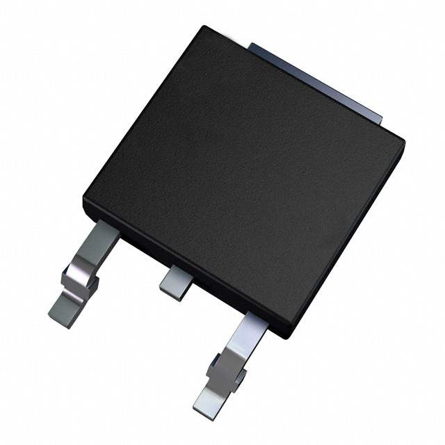
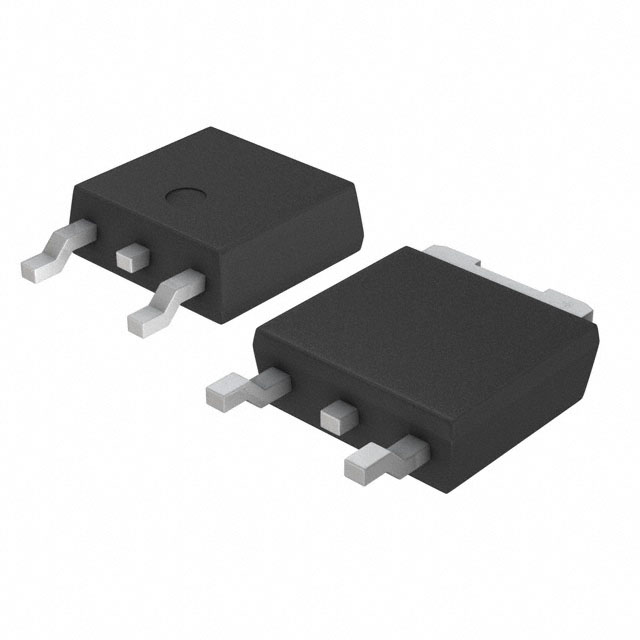
The IPD60R600P6 is an N-Channel 600V 7.3A MOSFET manufactured by Infineon Technologies in the CoolMOS™ P6 series, packaged in TO-252-3 (DPAK) surface mount configuration. This device is discontinued at DiGi Electronics, necessitating identification of functionally equivalent alternatives for ongoing design support and procurement.
The part operates across a temperature range of -55°C to 150°C (TJ) with a maximum power dissipation of 63W (Tc). Its primary application domain includes switching circuits requiring 600V blocking capability with moderate current handling at 7.3A continuous drain current.
Substiute Parts
Key Parameters
| Parameter | Value | Unit | Condition |
|---|---|---|---|
| Drain to Source Voltage (Vdss) | 600 | V | Blocking voltage rating |
| Continuous Drain Current (Id) @ 25°C | 7.3 | A | Tc condition |
| On-State Resistance (Rds On Max) | 600 | mOhm | @ 2.4A, 10V Vgs |
| Gate Charge (Qg Max) | 12 | nC | @ 10V Vgs |
| Input Capacitance (Ciss Max) | 557 | pF | @ 100V Vds |
| Power Dissipation (Max) | 63 | W | Tc condition |
| Operating Temperature Range | -55 to 150 | °C | TJ |
| Package Type | TO-252-3 DPAK | - | Surface Mount |
| Gate Voltage (Vgs Max) | ±20 | V | Absolute maximum |
Substitute Part Grouping Explanation
Substitution eligibility for the IPD60R600P6 is determined by strict adherence to the following electrical and mechanical parameters:
Primary Substitution Criteria:
- Drain to Source Voltage (Vdss): 600V (exact match required)
- Continuous Drain Current (Id): 7.3A minimum at 25°C Tc condition
- On-State Resistance (Rds On): 600mOhm maximum at specified gate voltage
- Package Type: TO-252-3 DPAK surface mount configuration
- FET Type: N-Channel MOSFET technology
- Operating Temperature Range: -55°C to 150°C minimum
Secondary Compatibility Parameters:
- Gate Charge (Qg): 12nC to 40nC range acceptable
- Input Capacitance (Ciss): 320pF to 1135pF range acceptable
- Gate Voltage (Vgs): ±20V to ±30V acceptable
- Power Dissipation: 60W to 90W acceptable range
Substitute parts must satisfy all primary criteria and fall within acceptable ranges for secondary parameters. Parts with higher current ratings (10A) or lower Rds On values are acceptable as they provide enhanced performance margins. Parts with discontinued or "Not For New Designs" status are included where electrical parameters match, but active product status is preferred for new applications.
Parameter Comparison
| Part Number | Manufacturer | Vdss (V) | Id @ 25°C (A) | Rds On Max (mOhm) | Qg Max (nC) | Ciss Max (pF) | Pd Max (W) | Status |
|---|---|---|---|---|---|---|---|---|
| IPD60R600P6 | Infineon | 600 | 7.3 | 600 | 12 | 557 | 63 | Discontinued |
| IPD60R600P6ATMA1 | Infineon | 600 | 7.3 | 600 | 12 | 557 | 63 | Active |
| AOD7S60 | Alpha & Omega | 600 | 7.0 | 600 | 8.2 | 372 | 83 | Not For New Designs |
| FCD600N60Z | onsemi | 600 | 7.4 | 600 | 26 | 1120 | 89 | Not For New Designs |
| FCD620N60ZF | onsemi | 600 | 7.3 | 620 | 36 | 1135 | 89 | Not For New Designs |
| FCD7N60TM-WS | onsemi | 600 | 7.0 | 600 | 30 | 920 | 83 | Not For New Designs |
| SIHD7N60E-GE3 | Vishay Siliconix | 600 | 7.0 | 600 | 40 | 680 | 78 | Active |
| STD10N60M2 | STMicroelectronics | 600 | 7.5 | 600 | 13.5 | 400 | 85 | Active |
| STD10NM60N | STMicroelectronics | 600 | 10.0 | 550 | 19 | 540 | 70 | Active |
| STD11NM60ND | STMicroelectronics | 600 | 10.0 | 450 | 30 | 850 | 90 | Active |
| STD9N60M2 | STMicroelectronics | 600 | 5.5 | 780 | 10 | 320 | 60 | Active |
Engineering Selection Recommendations
Preferred Direct Replacement:
IPD60R600P6ATMA1 (Infineon Technologies) is the primary recommended substitute. This part is the tape and reel packaged variant of the original IPD60R600P6, maintaining identical electrical specifications (600V, 7.3A, 600mOhm Rds On, 12nC gate charge) while offering active product status. This substitution requires no circuit redesign and provides pin-for-pin compatibility with identical thermal and electrical performance characteristics.
Active Product Alternatives (Preferred for New Designs):
STD10N60M2 (STMicroelectronics) provides a direct functional equivalent with active product status. Specifications include 600V Vdss, 7.5A continuous drain current, and 600mOhm Rds On. The slightly higher current rating (7.5A vs. 7.3A) and lower gate charge (13.5nC vs. 12nC) offer improved switching performance. This part is suitable for direct substitution in existing designs.
STD10NM60N (STMicroelectronics) offers enhanced performance with 10A continuous drain current and 550mOhm Rds On at 600V. This part provides superior current handling and reduced conduction losses, making it suitable for applications requiring higher reliability margins or increased thermal headroom.
SIHD7N60E-GE3 (Vishay Siliconix) maintains 600V, 7A continuous drain current, and 600mOhm Rds On specifications. Active product status and bulk packaging availability support procurement flexibility.
Discontinued Product Alternatives (Legacy Support Only):
AOD7S60, FCD600N60Z, FCD620N60ZF, and FCD7N60TM-WS meet electrical substitution criteria but carry "Not For New Designs" status. These parts are acceptable for replacement in existing production runs where supply continuity is required, but should not be selected for new circuit development.
Not Recommended:
STD9N60M2 exhibits reduced continuous drain current (5.5A) and elevated Rds On (780mOhm), making it unsuitable for applications requiring the full 7.3A specification. This part should be used only in current-limited applications.
All recommended substitutes maintain RoHS3 compliance, MSL 1 (Unlimited) moisture sensitivity rating, and REACH unaffected status consistent with the original IPD60R600P6.
Frequently Asked Questions (FAQ)
Q: Can IPD60R600P6ATMA1 be used as a direct replacement for IPD60R600P6?
A: Yes. IPD60R600P6ATMA1 is the tape and reel variant of the original part with identical electrical and thermal specifications. The only difference is packaging format (tape and reel vs. bulk). Pin configuration, package outline (TO-252-3 DPAK), and all electrical parameters are identical. No circuit modifications are required.
Q: What is the difference between STD10N60M2 and STD10NM60N?
A: Both parts operate at 600V with 10A continuous drain current. STD10N60M2 maintains 600mOhm Rds On (matching the original IPD60R600P6), while STD10NM60N reduces Rds On to 550mOhm, resulting in lower conduction losses and reduced heat generation. STD10NM60N is preferred for thermal-sensitive applications. Both are active products from STMicroelectronics.
Q: Why do some substitute parts have higher gate charge (Qg) values?
A: Gate charge affects switching speed and driver circuit requirements. The original IPD60R600P6 specifies 12nC gate charge. Substitute parts with higher Qg values (26nC to 40nC) require longer switching times but may offer other performance benefits such as improved thermal characteristics or lower Rds On. Circuit designers must verify gate driver capability to handle the specified gate charge without exceeding maximum switching frequency requirements.
Q: Are parts marked "Not For New Designs" acceptable for production use?
A: Parts with "Not For New Designs" status (AOD7S60, FCD600N60Z, FCD620N60ZF, FCD7N60TM-WS) meet all electrical substitution criteria and are acceptable for replacement in existing production runs where supply continuity is required. However, these parts should not be selected for new circuit development. For new designs, select from active product alternatives: IPD60R600P6ATMA1, STD10N60M2, STD10NM60N, or SIHD7N60E-GE3.
Q: What is the significance of the TO-252-3 DPAK package specification?
A: TO-252-3 DPAK (2 Leads + Tab) is the surface mount package standard for all listed substitutes. This package provides three connection points: Gate, Source, and Drain (via tab). All substitute parts maintain identical package outline (SC-63), pin configuration, and thermal interface characteristics. PCB layout modifications are not required when substituting between parts with this package type.
Q: Can STD11NM60ND be used in place of IPD60R600P6?
A: STD11NM60ND is electrically compatible at 600V with 10A continuous drain current and 450mOhm Rds On. However, the higher current rating and lower Rds On represent performance enhancement rather than direct equivalence. This part is suitable for applications where the original 7.3A specification is conservative or where reduced conduction losses are beneficial. Verify that the application circuit can accommodate the enhanced performance characteristics without adverse effects.
Q: What compliance certifications apply to all substitute parts?
A: All listed substitute parts maintain RoHS3 compliance, MSL 1 (Unlimited) moisture sensitivity rating, and REACH unaffected status. ECCN classification is EAR99 for all parts. HTSUS code 8541.29.0095 applies uniformly. These certifications ensure regulatory compliance for commercial and industrial applications across all major markets.
Q: How does input capacitance (Ciss) variation affect circuit design?
A: Input capacitance ranges from 320pF (STD9N60M2) to 1135pF (FCD620N60ZF) across substitute options. Higher Ciss values increase gate driver current requirements and may affect switching speed. The original IPD60R600P6 specifies 557pF. Substitutes with significantly different Ciss values (particularly FCD600N60Z at 1120pF) may require gate driver circuit verification to ensure adequate current sourcing capability and acceptable switching frequency performance.
Q: Is packaging format (bulk vs. tape and reel) a substitution consideration?
A: Packaging format affects procurement and assembly processes but does not impact electrical or thermal performance. IPD60R600P6ATMA1 is supplied in tape and reel format, while the original IPD60R600P6 was bulk packaged. Both formats contain identical die and electrical specifications. Select packaging format based on assembly equipment capability and procurement volume requirements.
Alternative Parts

SJ6012L2TP
Littelfuse Inc.
6 Alternative Parts

JMK107BBJ476MA-RE
Taiyo Yuden
10 Alternative Parts

GMK107BBJ475MA-T
Taiyo Yuden
5 Alternative Parts
SJ6020N2ARP
Littelfuse Inc.
3 Alternative Parts
SJ6025R2ATP
Littelfuse Inc.
4 Alternative Parts

2474-05L
API Delevan Inc.
1 Alternative Parts

4590R-684K
API Delevan Inc.
1 Alternative Parts

CM6560R-334
API Delevan Inc.
1 Alternative Parts

CM6460-104
API Delevan Inc.
1 Alternative Parts

5526-12
API Delevan Inc.
1 Alternative Parts