


Request Quote
(Ships tomorrow)
IPA65R310CFDXKSA1 N-Channel 650V 11.4A MOSFET Equivalent & Substitute Parts
Part Overview
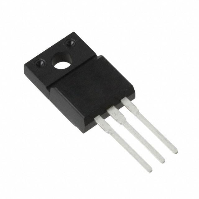
The IPA65R310CFDXKSA1 is an N-Channel 650V 11.4A MOSFET manufactured by Infineon Technologies in the CoolMOS™ series. This device is rated for 32W power dissipation and features a TO-220-3 through-hole package. The part is classified as obsolete, making equivalent and substitute parts necessary for ongoing design support and procurement.
Substitute parts must maintain electrical compatibility across drain-source voltage (Vdss), continuous drain current (Id), on-state resistance (Rds On), and gate charge characteristics while accommodating through-hole mounting in TO-220 package variants.
Substiute Parts
Key Parameters
| Parameter | Value | Unit | Specification Condition |
|---|---|---|---|
| Drain to Source Voltage (Vdss) | 650 | V | Maximum rating |
| Continuous Drain Current (Id) @ 25°C | 11.4 | A | Tc (case temperature) |
| On-State Resistance (Rds On) | 310 | mOhm | @ 4.4A, Vgs = 10V |
| Gate Threshold Voltage (Vgs(th)) | 4.5 | V | @ 440µA |
| Gate Charge (Qg) | 41 | nC | @ Vgs = 10V |
| Input Capacitance (Ciss) | 1100 | pF | @ Vds = 100V |
| Power Dissipation (Max) | 32 | W | Tc |
| Operating Temperature Range | -55 to 150 | °C | TJ (junction) |
| Package Type | TO-220-3 | — | Through-hole |
| Gate Drive Voltage | 10 | V | Maximum Rds On specification |
Substitute Part Grouping Explanation
Substitution eligibility is determined by the following criteria applied strictly to the provided parameters:
Primary Compatibility Criteria:
- Drain-Source Voltage (Vdss): Must equal or exceed 650V
- Continuous Drain Current (Id): Must equal or exceed 11.4A at 25°C case temperature
- On-State Resistance (Rds On): Must not exceed 310mOhm at specified gate drive voltage (10V)
- Gate Charge (Qg): Lower values indicate improved switching performance; values up to 68nC are acceptable
- Operating Temperature Range: Must support -55°C to 150°C minimum
- Package: TO-220 through-hole variants (TO-220-3, TO-220-3F, TO-220FP, TO-220 Isolated Tab)
- Compliance: RoHS3 compliant, MSL Level 1
Substitute Parts Classified by Electrical Equivalence:
Group 1 - Direct Electrical Equivalents (Vdss 650V, Id ≥11.4A, Rds On ≤310mOhm):
- IPA65R310CFDXKSA2 (Infineon, Active, CoolMOS™ CFD2 series)
- IXTP12N65X2M (IXYS, Active, Ultra X2 series)
- STF15N65M5 (STMicroelectronics, Active, MDmesh™ V series)
- STF15NM65N (STMicroelectronics, Active, MDmesh™ II series)
- STF16N65M5 (STMicroelectronics, Active, MDmesh™ V series)
Group 2 - Functional Equivalents (Vdss 650V, Id 11-12A, Rds On 340-399mOhm):
- AOTF11S65L (Alpha & Omega Semiconductor, Active, aMOS™ series)
Group 3 - Higher Current Capability (Vdss 650V, Id ≥18A, Rds On ≤390mOhm):
- AOTF18N65 (Alpha & Omega Semiconductor, Active)
Group 4 - Reduced Voltage Rating (Vdss 600V, Id ≥11A, Rds On ≤360mOhm):
- STF13NM60N (STMicroelectronics, Active, MDmesh™ II series)
- R6015FNX (Rohm Semiconductor, Active)
Group 5 - Lower Current Rating (Vdss 650V, Id 8.5A, Rds On ≤430mOhm):
- STF12N65M5 (STMicroelectronics, Active, MDmesh™ V series)
Parameter Comparison
| Manufacturer Part Number | Manufacturer | Vdss (V) | Id @ 25°C (A) | Rds On (mOhm) | Qg (nC) | Ciss (pF) | Power Diss. (W) | Status | Package |
|---|---|---|---|---|---|---|---|---|---|
| IPA65R310CFDXKSA1 | Infineon | 650 | 11.4 | 310 | 41 | 1100 | 32 | Obsolete | TO-220-3 |
| IPA65R310CFDXKSA2 | Infineon | 650 | 11.4 | 310 | 41 | 1100 | 32 | Active | TO-220-3 FP |
| AOTF11S65L | Alpha & Omega | 650 | 11 | 399 | 13.2 | 646 | 31 | Active | TO-220-3F |
| AOTF18N65 | Alpha & Omega | 650 | 18 | 390 | 68 | 3785 | 50 | Active | TO-220-3F |
| IXTP12N65X2M | IXYS | 650 | 12 | 300 | 17.7 | 1100 | 40 | Active | TO-220 Isolated Tab |
| R6015FNX | Rohm | 600 | 15 | 350 | 42 | 1660 | 77 | Active | TO-220FM |
| STF12N65M5 | STMicroelectronics | 650 | 8.5 | 430 | 22 | 900 | 25 | Active | TO-220FP |
| STF13NM60N | STMicroelectronics | 600 | 11 | 360 | 30 | 790 | 25 | Active | TO-220FP |
| STF15N65M5 | STMicroelectronics | 650 | 11 | 340 | 22 | 816 | 30 | Active | TO-220FP |
| STF15NM65N | STMicroelectronics | 650 | 12 | 380 | 33.3 | 983 | 30 | Active | TO-220FP |
| STF16N65M5 | STMicroelectronics | 650 | 12 | 299 | 45 | 1250 | 25 | Active | TO-220FP |
Engineering Selection Recommendations
Recommended Primary Substitute:
IPA65R310CFDXKSA2 (Infineon Technologies) is the recommended direct replacement. This part maintains identical electrical specifications (650V, 11.4A, 310mOhm Rds On, 41nC gate charge) and is the active production variant of the obsolete IPA65R310CFDXKSA1. Product status is Active with full RoHS3 compliance and MSL Level 1 rating. Packaging differs only in format designation (PG-TO220-FP versus PG-TO220-3-111), both compatible with standard TO-220-3 through-hole PCB layouts.
Secondary Substitutes by Application Requirement:
For applications requiring improved on-state resistance performance at 650V rating: STF16N65M5 (299mOhm) or IXTP12N65X2M (300mOhm) provide lower Rds On values, reducing conduction losses. Both are Active status with full compliance certifications.
For applications tolerating reduced voltage rating (600V acceptable): STF13NM60N offers 11A continuous current with 360mOhm Rds On and extensive inventory availability (85,270 units). R6015FNX (Rohm) supports higher current (15A) with 600V rating and 77W power dissipation capability.
For applications requiring higher current capacity: AOTF18N65 (18A, 650V, 390mOhm) provides increased current margin with Active status and full compliance.
All recommended substitutes maintain through-hole TO-220 package compatibility, -55°C to 150°C operating temperature range, RoHS3 compliance, and MSL Level 1 moisture sensitivity rating.
Frequently Asked Questions (FAQ)
Q: Can IPA65R310CFDXKSA2 directly replace IPA65R310CFDXKSA1 without PCB modification?
A: Yes. Both parts use TO-220-3 through-hole package format with identical pin configuration and electrical specifications. PCB layout requires no changes. The packaging designation difference (PG-TO220-FP versus PG-TO220-3-111) reflects manufacturing format only and does not affect electrical or mechanical compatibility.
Q: What is the minimum drain-source voltage rating acceptable for substitution?
A: The original part specifies 650V Vdss. Substitutes with 600V rating (STF13NM60N, R6015FNX) are acceptable only when the application circuit operates below 600V. Designs utilizing the full 650V rating must use 650V-rated substitutes to maintain design margin and reliability.
Q: How does on-state resistance affect substitution suitability?
A: The original part specifies 310mOhm maximum Rds On at 4.4A, 10V gate drive. Substitutes with lower Rds On values (IXTP12N65X2M at 300mOhm, STF16N65M5 at 299mOhm) reduce conduction losses and heat dissipation, improving efficiency. Substitutes with higher Rds On values (AOTF11S65L at 399mOhm, R6015FNX at 350mOhm) increase conduction losses and require thermal design verification. Selection depends on thermal budget and efficiency requirements.
Q: Are TO-220-3F and TO-220FP packages compatible with TO-220-3 PCB footprints?
A: TO-220-3F and TO-220FP are mechanical variants of the TO-220-3 package with identical pin spacing and lead positions. All three formats are compatible with standard TO-220-3 through-hole PCB layouts. The suffix designations indicate manufacturing or thermal interface variations that do not affect electrical performance or mechanical fit.
Q: What is the significance of gate charge (Qg) differences between substitutes?
A: Gate charge affects switching speed and gate drive circuit requirements. The original part specifies 41nC at 10V. Substitutes with lower Qg (AOTF11S65L at 13.2nC, IXTP12N65X2M at 17.7nC, STF12N65M5 at 22nC) enable faster switching and reduce gate drive power consumption. Substitutes with higher Qg (AOTF18N65 at 68nC) require longer switching times. Gate drive circuits must be verified for compatibility with the selected substitute's Qg specification.
Q: Can STF12N65M5 substitute for IPA65R310CFDXKSA1 despite lower continuous current rating?
A: STF12N65M5 is rated for 8.5A continuous current versus the original 11.4A specification. This part is suitable only for applications where actual continuous drain current does not exceed 8.5A. Applications requiring the full 11.4A rating must use substitutes with equivalent or higher current ratings (IPA65R310CFDXKSA2, IXTP12N65X2M, AOTF11S65L, AOTF18N65, STF15N65M5, STF15NM65N, STF16N65M5).
Q: What compliance certifications apply to all recommended substitutes?
A: All substitute parts listed maintain RoHS3 compliance and MSL Level 1 (Unlimited) moisture sensitivity rating, matching the original part's compliance profile. REACH status is Unaffected for all parts. ECCN classification is EAR99 and HTSUS code is 8541.29.0095 across all substitutes, enabling equivalent procurement and supply chain handling.
Q: How should thermal design be adjusted when selecting substitutes with different power dissipation ratings?
A: The original part specifies 32W maximum power dissipation. Substitutes with lower ratings (STF12N65M5 at 25W, STF13NM60N at 25W, STF15N65M5 at 30W, STF15NM65N at 30W, STF16N65M5 at 25W) require verification that actual circuit power dissipation remains within the selected part's rating. Substitutes with higher ratings (AOTF18N65 at 50W, R6015FNX at 77W) provide additional thermal margin. Thermal design must account for both the part's power dissipation rating and the circuit's actual operating conditions.
Alternative Parts

SJ6012L2TP
Littelfuse Inc.
6 Alternative Parts

JMK107BBJ476MA-RE
Taiyo Yuden
10 Alternative Parts

GMK107BBJ475MA-T
Taiyo Yuden
5 Alternative Parts
SJ6020N2ARP
Littelfuse Inc.
3 Alternative Parts
SJ6025R2ATP
Littelfuse Inc.
4 Alternative Parts

2474-05L
API Delevan Inc.
1 Alternative Parts

4590R-684K
API Delevan Inc.
1 Alternative Parts

CM6560R-334
API Delevan Inc.
1 Alternative Parts

CM6460-104
API Delevan Inc.
1 Alternative Parts

5526-12
API Delevan Inc.
1 Alternative Parts