


Request Quote
(Ships tomorrow)
IPA65R110CFDXKSA1 Equivalent & Substitute Parts
Part Overview
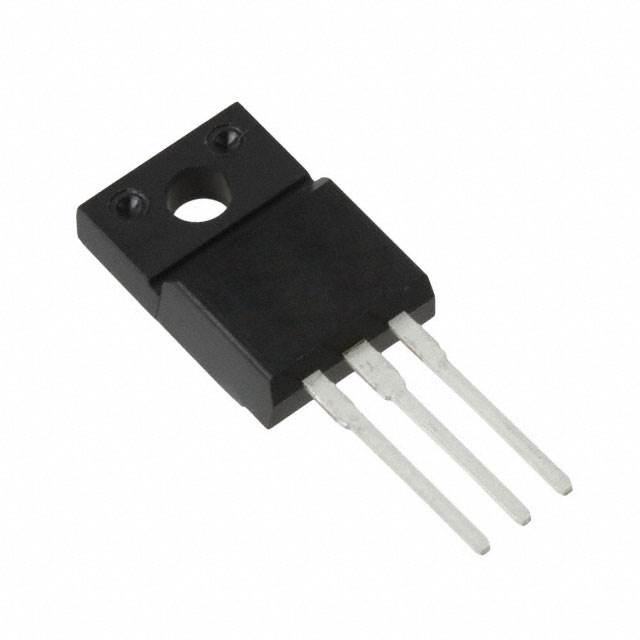
The IPA65R110CFDXKSA1 is an N-Channel 650V 31.2A MOSFET manufactured by Infineon Technologies in the CoolMOS™ series, housed in a TO-220-3 through-hole package. This device is classified as obsolete, necessitating identification of equivalent and substitute components for ongoing design support and procurement continuity. The part delivers 34.7W maximum power dissipation and operates across a temperature range of -55°C to 150°C (TJ).
Substiute Parts
Key Parameters
| Parameter | Value | Unit |
|---|---|---|
| Drain to Source Voltage (Vdss) | 650 | V |
| Continuous Drain Current (Id) @ 25°C | 31.2 | A (Tc) |
| On-State Resistance (Rds On) @ 12.7A, 10V | 110 | mOhm |
| Gate Threshold Voltage (Vgs(th)) @ 1.3mA | 4.5 | V |
| Gate Charge (Qg) @ 10V | 118 | nC |
| Input Capacitance (Ciss) @ 100V | 3240 | pF |
| Power Dissipation (Max) | 34.7 | W (Tc) |
| Operating Temperature Range | -55 to 150 | °C (TJ) |
| Package Type | TO-220-3 | Through Hole |
| Gate Voltage (Max) | ±20 | V |
Substitute Part Grouping Explanation
Substitution eligibility for the IPA65R110CFDXKSA1 is determined by the following critical parameters:
Primary Substitution Criteria:
- Drain to Source Voltage (Vdss): 650V minimum
- Continuous Drain Current (Id): 31.2A or greater
- On-State Resistance (Rds On): 110mOhm or lower at specified gate voltage
- Package Type: TO-220-3 through-hole configuration
- Technology: N-Channel MOSFET
Secondary Compatibility Factors:
- Gate Threshold Voltage (Vgs(th)): 4.5V maximum
- Operating Temperature Range: -55°C to 150°C minimum
- RoHS3 Compliance and REACH Unaffected status
The substitute parts are grouped into two categories:
Category 1 - Parametric Equivalent (Identical Electrical Performance): IPA65R110CFDXKSA2 maintains all electrical specifications of the main part while differing only in packaging format (Tube vs. standard packaging) and product status (Active vs. Obsolete).
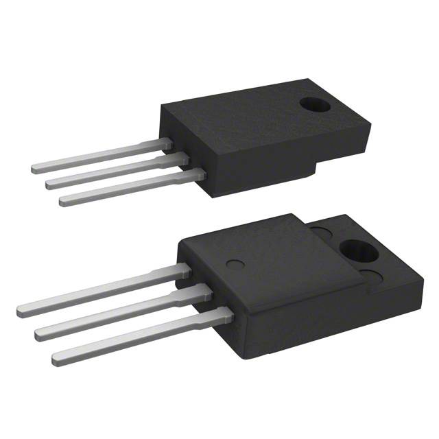
Category 2 - Functional Substitutes (Acceptable Performance Trade-offs): STF34N65M5, STF31N65M5, STF33N60M2, and STF34NM60ND provide equivalent or superior electrical performance within the 600V–650V voltage class, with drain currents ranging from 22A to 29A and on-state resistances from 110mOhm to 148mOhm. These parts accommodate applications where the full 31.2A specification is not required or where minor voltage derating is acceptable.
Parameter Comparison
| Parameter | IPA65R110CFDXKSA1 | IPA65R110CFDXKSA2 | STF34N65M5 | STF31N65M5 | STF33N60M2 | STF34NM60ND |
|---|---|---|---|---|---|---|
| Manufacturer | Infineon | Infineon | STMicroelectronics | STMicroelectronics | STMicroelectronics | STMicroelectronics |
| Vdss (V) | 650 | 650 | 650 | 650 | 600 | 600 |
| Id @ 25°C (A) | 31.2 | 31.2 | 28 | 22 | 26 | 29 |
| Rds On @ 10V (mOhm) | 110 | 110 | 110 | 148 | 125 | 110 |
| Vgs(th) @ Id (V) | 4.5 | 4.5 | 5 | 5 | 4 | 5 |
| Qg @ 10V (nC) | 118 | 118 | 70 | 45 | 45.5 | 80.4 |
| Ciss @ 100V (pF) | 3240 | 3240 | 2590 | 816 | 1781 | 2785 |
| Power Dissipation (W) | 34.7 | 34.7 | 35 | 30 | 35 | 40 |
| Operating Temp Range (°C) | -55 to 150 | -55 to 150 | -55 to 150 | -55 to 150 | -55 to 150 | -55 to 150 |
| Package | TO-220-3 | TO-220-3 | TO-220FP | TO-220FP | TO-220FP | TO-220FP |
| Product Status | Obsolete | Active | Active | Active | Active | Active |
| RoHS Status | ROHS3 Compliant | ROHS3 Compliant | ROHS3 Compliant | ROHS3 Compliant | ROHS3 Compliant | ROHS3 Compliant |
| REACH Status | REACH Unaffected | REACH Unaffected | REACH Unaffected | REACH Unaffected | REACH Unaffected | REACH Unaffected |
Engineering Selection Recommendations
Direct Replacement (Recommended for Obsolescence Mitigation):
IPA65R110CFDXKSA2 is the primary recommendation for direct substitution. This part maintains identical electrical specifications (650V, 31.2A, 110mOhm Rds On, 118nC gate charge) while offering active product status and improved supply availability (2011 units in stock versus 872 units for the obsolete IPA65R110CFDXKSA1). Both parts carry ROHS3 compliance and REACH Unaffected certification. The only distinction is packaging format (Tube for IPA65R110CFDXKSA2), which does not affect electrical performance or PCB-level compatibility.
Alternative Substitutes (Application-Dependent Selection):
STF34N65M5 provides equivalent 650V voltage rating and 110mOhm on-state resistance with 28A continuous drain current. This part is suitable for applications where the full 31.2A specification is not required. The reduced gate charge (70nC versus 118nC) and input capacitance (2590pF versus 3240pF) offer improved switching performance characteristics.
STF34NM60ND operates at 600V (50V derating from the original 650V specification) with 29A continuous drain current and 110mOhm on-state resistance. This part is applicable to designs with 600V system voltage or where 50V margin reduction is acceptable. The higher power dissipation rating (40W versus 34.7W) provides thermal headroom.
STF31N65M5 and STF33N60M2 are suitable only for applications with reduced current requirements (22A and 26A respectively) and are not recommended as primary substitutes due to current derating.
All substitute parts maintain ROHS3 compliance, REACH Unaffected status, and through-hole TO-220 package compatibility with the original design.
Frequently Asked Questions (FAQ)
Q1: Can IPA65R110CFDXKSA2 be used as a direct drop-in replacement for IPA65R110CFDXKSA1?
A: Yes. IPA65R110CFDXKSA2 is a parametric equivalent with identical electrical specifications (650V, 31.2A, 110mOhm Rds On). The parts differ only in packaging format (Tube versus standard packaging) and product status (Active versus Obsolete). PCB layout, gate drive circuitry, and thermal management remain unchanged.
Q2: What is the significance of the voltage rating difference between 650V and 600V substitutes?
A: The 650V rating of the original part provides a 50V safety margin above typical 600V system voltages. Substitutes rated at 600V (STF33N60M2, STF34NM60ND) eliminate this margin and are suitable only for designs with confirmed 600V maximum operating voltage. For 650V system designs, 650V-rated substitutes (STF34N65M5, STF31N65M5) are required.
Q3: How does the gate charge (Qg) difference affect circuit performance?
A: Gate charge determines the energy required to switch the MOSFET on and off. The original part specifies 118nC at 10V. Substitutes with lower gate charge (STF34N65M5 at 70nC, STF31N65M5 at 45nC) reduce gate drive power dissipation and enable faster switching transitions. Substitutes with higher gate charge (STF34NM60ND at 80.4nC) require proportionally more gate drive energy but remain compatible with standard gate drive circuits.
Q4: Are all substitute parts compatible with the existing PCB layout?
A: All substitute parts use TO-220-3 through-hole or TO-220FP package configurations with identical pin assignments and mechanical dimensions. PCB footprints, lead spacing, and mounting hole positions are compatible. Thermal interface requirements (heatsink mounting) remain unchanged.
Q5: What is the impact of reduced drain current ratings in STF31N65M5 (22A) and STF33N60M2 (26A)?
A: These parts are suitable only for applications where the maximum continuous drain current requirement is 22A or 26A respectively. For designs requiring the full 31.2A specification, these substitutes will cause thermal stress and potential device failure. Current derating of 29% (STF31N65M5) or 17% (STF33N60M2) from the original specification makes these parts unsuitable as primary replacements.
Q6: Do all substitute parts maintain regulatory compliance?
A: Yes. All substitute parts listed carry ROHS3 compliance and REACH Unaffected certification, matching the regulatory status of the original IPA65R110CFDXKSA1. No additional compliance documentation or design review is required for regulatory purposes.
Q7: Which substitute offers the best thermal performance?
A: STF34NM60ND provides the highest power dissipation rating at 40W (versus 34.7W for the original part), offering 15% additional thermal headroom. However, this part operates at 600V (50V derating) and is suitable only for 600V system designs. For 650V designs requiring maximum thermal margin, STF34N65M5 at 35W is recommended.
Q8: How should gate drive voltage be adjusted for different substitute parts?
A: All substitute parts accept gate voltages within ±20V to ±25V range. The original part specifies ±20V maximum; substitutes specify ±25V maximum. Existing gate drive circuits designed for ±20V operation are compatible with all substitutes. No gate drive circuit modifications are required.
Alternative Parts

SJ6012L2TP
Littelfuse Inc.
6 Alternative Parts

JMK107BBJ476MA-RE
Taiyo Yuden
10 Alternative Parts

GMK107BBJ475MA-T
Taiyo Yuden
5 Alternative Parts
SJ6020N2ARP
Littelfuse Inc.
3 Alternative Parts
SJ6025R2ATP
Littelfuse Inc.
4 Alternative Parts

2474-05L
API Delevan Inc.
1 Alternative Parts

4590R-684K
API Delevan Inc.
1 Alternative Parts

CM6560R-334
API Delevan Inc.
1 Alternative Parts

CM6460-104
API Delevan Inc.
1 Alternative Parts

5526-12
API Delevan Inc.
1 Alternative Parts