


Request Quote
(Ships tomorrow)
INA129PA Instrumentation Amplifier Equivalent & Substitute Parts
Part Overview
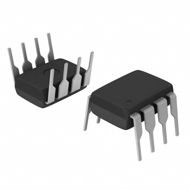
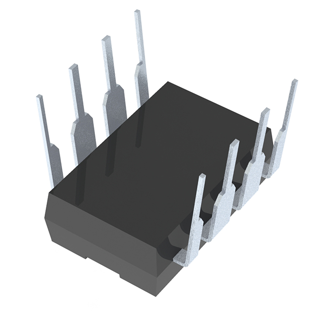
The INA129PA is a single-circuit instrumentation amplifier manufactured by Texas Instruments in 8-PDIP through-hole packaging. This device is classified as an active linear amplifier with an operating temperature range of -40°C to 85°C and is currently in active product status. The INA129PA is designed for precision signal conditioning applications requiring low input bias current and low input offset voltage. Equivalent and substitute parts are identified based on matching electrical performance parameters, mechanical compatibility, and packaging specifications to ensure direct functional replacement in circuit designs.
Substiute Parts
Key Parameters
| Parameter | INA129PA Value | Unit | Substitution Relevance |
|---|---|---|---|
| Amplifier Type | Instrumentation | — | Core functional classification |
| Number of Circuits | 1 | — | Channel count must match |
| Slew Rate | 4 | V/µs | Signal bandwidth capability |
| -3dB Bandwidth | 1.3 | MHz | Frequency response specification |
| Current - Input Bias | 2 | nA | Input impedance characteristic |
| Voltage - Input Offset | 25 | µV | DC accuracy specification |
| Current - Supply | 700 | µA | Power consumption |
| Current - Output / Channel | 15 | mA | Output drive capability |
| Voltage - Supply Span (Min) | 4.5 | V | Minimum operating voltage |
| Voltage - Supply Span (Max) | 36 | V | Maximum operating voltage |
| Operating Temperature | -40 to 85 | °C | Environmental operating range |
| Mounting Type | Through Hole | — | PCB assembly compatibility |
| Package / Case | 8-DIP (0.300", 7.62mm) | — | Physical footprint and pinout |
| RoHS Status | ROHS3 Compliant | — | Environmental compliance |
Substitute Part Grouping Explanation
Substitution of the INA129PA is determined by strict alignment of electrical and mechanical parameters. The following criteria establish valid substitute relationships:
Primary Matching Criteria:
- Amplifier Type: Must be Instrumentation
- Number of Circuits: Must equal 1
- Package / Case: Must be 8-DIP (0.300", 7.62mm)
- Mounting Type: Must be Through Hole
- Voltage - Supply Span: Substitute minimum must be ≤4.5V; substitute maximum must be ≥36V
- Operating Temperature: Substitute range must encompass or match -40°C to 85°C
Secondary Performance Parameters:
- Slew Rate: Substitute value should support equivalent or superior signal bandwidth
- -3dB Bandwidth: Substitute value should support equivalent or superior frequency response
- Current - Input Bias: Lower values indicate superior input impedance characteristics
- Voltage - Input Offset: Lower values indicate superior DC accuracy
- Current - Supply: Lower values indicate superior power efficiency
- Current - Output / Channel: Must support minimum 15 mA output drive
Compliance Requirements:
- RoHS Status: ROHS3 Compliant (mandatory)
- REACH Status: REACH Unaffected (mandatory)
- Product Status: Active (mandatory)
Substitute parts identified: AD620ANZ, AD620BNZ, AD621ANZ, AD622ANZ, AMP02EPZ, AMP02FPZ, LT1167CN8#PBF, LT1167IN8#PBF, LT1168ACN8#PBF, LT1920CN8#PBF.
Parameter Comparison
| Part Number | Manufacturer | Slew Rate (V/µs) | Bandwidth (MHz) | Input Bias (nA/pA) | Input Offset (µV) | Supply Current (µA) | Output Current (mA) | Supply Min (V) | Supply Max (V) | Temp Range (°C) |
|---|---|---|---|---|---|---|---|---|---|---|
| INA129PA | Texas Instruments | 4 | 1.3 | 2 nA | 25 | 700 | 15 | 4.5 | 36 | -40 to 85 |
| AD620ANZ | Analog Devices Inc. | 1.2 | 1 | 500 pA | 30 | 900 | 18 | 4.6 | 36 | -40 to 85 |
| AD620BNZ | Analog Devices Inc. | 1.2 | 1 | 500 pA | 15 | 900 | 18 | 4.6 | 36 | -40 to 85 |
| AD621ANZ | Analog Devices Inc. | 1.2 | 0.8 | 500 pA | 75 | 900 | 18 | 4.6 | 36 | -40 to 85 |
| AD622ANZ | Analog Devices Inc. | 1.2 | 1 | 2 nA | 60 | 900 | 18 | 5.2 | 36 | -40 to 85 |
| AMP02EPZ | Analog Devices Inc. | 6 | 1.2 | 2 nA | 20 | 5000 | 32 | 9 | 36 | -40 to 85 |
| AMP02FPZ | Analog Devices Inc. | 6 | 1.2 | 4 nA | 40 | 5000 | 32 | 9 | 36 | -40 to 85 |
| LT1167CN8#PBF | Analog Devices Inc. | 1.2 | 1 | 80 pA | 20 | 900 | — | 4.6 | 36 | 0 to 70 |
| LT1167IN8#PBF | Analog Devices Inc. | 1.2 | 1 | 80 pA | 20 | 900 | 27 | 4.6 | 36 | -40 to 85 |
| LT1168ACN8#PBF | Analog Devices Inc. | 0.5 | 0.4 | 40 pA | 15 | 350 | 32 | 4.6 | 36 | 0 to 70 |
| LT1920CN8#PBF | Analog Devices Inc. | 1.2 | 1 | 500 pA | 30 | 900 | — | 4.6 | 36 | 0 to 70 |
Engineering Selection Recommendations
Full-Range Temperature Substitutes (-40°C to 85°C):
The following parts maintain the complete operating temperature range of the INA129PA:
- AD620ANZ: Matches supply voltage range, provides superior input bias current (500 pA vs. 2 nA), slightly higher supply current (900 µA vs. 700 µA), and equivalent output drive capability (18 mA vs. 15 mA).
- AD620BNZ: Identical to AD620ANZ with improved input offset voltage (15 µV vs. 25 µV).
- AD621ANZ: Matches supply voltage range with reduced bandwidth (0.8 MHz vs. 1.3 MHz) and elevated input offset voltage (75 µV).
- AD622ANZ: Matches input bias current specification (2 nA), requires minimum supply voltage of 5.2V (vs. 4.5V for INA129PA).
- AMP02EPZ: Provides superior slew rate (6 V/µs vs. 4 V/µs) and output drive capability (32 mA vs. 15 mA), requires minimum supply voltage of 9V and higher supply current (5 mA vs. 700 µA).
- AMP02FPZ: Identical performance to AMP02EPZ with slightly higher input offset voltage (40 µV vs. 20 µV).
- LT1167IN8#PBF: Matches supply voltage range, provides superior input bias current (80 pA vs. 2 nA) and input offset voltage (20 µV vs. 25 µV), equivalent output drive capability (27 mA vs. 15 mA).
Limited Temperature Range Substitutes (0°C to 70°C):
The following parts operate within a narrower temperature range and are suitable only for applications not requiring full -40°C to 85°C coverage:
- LT1167CN8#PBF: Provides superior input bias current (80 pA) and input offset voltage (20 µV), operating temperature limited to 0°C to 70°C.
- LT1168ACN8#PBF: Provides lowest supply current (350 µA vs. 700 µA), superior input bias current (40 pA), and lowest input offset voltage (15 µV), operating temperature limited to 0°C to 70°C, reduced bandwidth (0.4 MHz vs. 1.3 MHz).
- LT1920CN8#PBF: Matches AD620ANZ performance characteristics, operating temperature limited to 0°C to 70°C.
Compliance Status:
All identified substitute parts maintain ROHS3 compliance, REACH unaffected status, and active product status, ensuring regulatory and supply chain continuity.
Frequently Asked Questions (FAQ)
Q1: Can AD620ANZ directly replace INA129PA in all applications?
AD620ANZ is mechanically and electrically compatible with INA129PA across the full -40°C to 85°C operating temperature range. Both devices are 8-DIP through-hole packages with identical pinouts. AD620ANZ provides superior input bias current performance (500 pA vs. 2 nA) and maintains equivalent output drive capability. Supply voltage compatibility is confirmed: AD620ANZ operates from 4.6V minimum (vs. 4.5V for INA129PA) to 36V maximum. The primary difference is slightly higher supply current consumption (900 µA vs. 700 µA). Direct substitution is valid for applications where this power consumption increase is acceptable.
Q2: What is the difference between AD620ANZ and AD620BNZ?
AD620ANZ and AD620BNZ are identical except for input offset voltage specification. AD620BNZ provides tighter input offset voltage tolerance (15 µV vs. 30 µV for AD620ANZ). Both devices share identical slew rate (1.2 V/µs), bandwidth (1 MHz), input bias current (500 pA), supply current (900 µA), and output drive capability (18 mA). Selection between these parts depends on DC accuracy requirements of the application.
Q3: Why do LT1167CN8#PBF and LT1167IN8#PBF have different temperature ranges?
LT1167CN8#PBF operates from 0°C to 70°C, while LT1167IN8#PBF operates from -40°C to 85°C. Both devices are identical in electrical performance and package type. The temperature range designation reflects the manufacturing grade and testing requirements. For applications requiring full -40°C to 85°C coverage, LT1167IN8#PBF is the appropriate selection. For applications limited to 0°C to 70°C, either part is acceptable.
Q4: Can AMP02EPZ or AMP02FPZ replace INA129PA in low-power applications?
AMP02EPZ and AMP02FPZ are not suitable for low-power applications. These devices require minimum supply voltage of 9V (vs. 4.5V for INA129PA) and consume significantly higher supply current (5 mA vs. 700 µA). However, AMP02EPZ and AMP02FPZ provide superior slew rate (6 V/µs vs. 4 V/µs) and output drive capability (32 mA vs. 15 mA), making them suitable for high-speed, high-current output applications where supply voltage and power consumption constraints are not limiting factors.
Q5: What is the significance of input bias current differences among substitute parts?
Input bias current determines the input impedance of the instrumentation amplifier. Lower input bias current values indicate higher input impedance. INA129PA specifies 2 nA input bias current. Substitute parts offer varying input bias current specifications: AD620 series provides 500 pA (superior), LT1167 series provides 80 pA (superior), and LT1168ACN8#PBF provides 40 pA (superior). For applications with high-impedance signal sources, lower input bias current reduces signal loading errors. For applications with low-impedance sources, input bias current differences are negligible.
Q6: Are all substitute parts available in the same packaging?
All identified substitute parts are available in 8-DIP (0.300", 7.62mm) through-hole packaging with identical pinout compatibility to INA129PA. Mechanical substitution is direct without PCB layout modifications. All parts are ROHS3 compliant and REACH unaffected, ensuring environmental and regulatory compliance equivalence.
Q7: Which substitute part provides the lowest power consumption?
LT1168ACN8#PBF provides the lowest supply current at 350 µA (vs. 700 µA for INA129PA). However, LT1168ACN8#PBF operates within a narrower temperature range (0°C to 70°C vs. -40°C to 85°C) and provides reduced bandwidth (0.4 MHz vs. 1.3 MHz). For applications requiring full temperature range coverage and higher bandwidth, AD620ANZ or LT1167IN8#PBF are more appropriate selections despite higher supply current consumption.
Q8: What is the minimum supply voltage requirement for each substitute part?
INA129PA requires minimum 4.5V supply voltage. Substitute parts specify the following minimum supply voltages: AD620 series (4.6V), AD621ANZ (4.6V), AD622ANZ (5.2V), AMP02 series (9V), LT1167 series (4.6V), and LT1168ACN8#PBF (4.6V). For applications with supply voltages below 5.2V, AD622ANZ is not suitable. For applications with supply voltages below 9V, AMP02 series parts are not suitable.
Alternative Parts

SJ6012L2TP
Littelfuse Inc.
6 Alternative Parts

JMK107BBJ476MA-RE
Taiyo Yuden
10 Alternative Parts

GMK107BBJ475MA-T
Taiyo Yuden
5 Alternative Parts
SJ6020N2ARP
Littelfuse Inc.
3 Alternative Parts
SJ6025R2ATP
Littelfuse Inc.
4 Alternative Parts

2474-05L
API Delevan Inc.
1 Alternative Parts

4590R-684K
API Delevan Inc.
1 Alternative Parts

CM6560R-334
API Delevan Inc.
1 Alternative Parts

CM6460-104
API Delevan Inc.
1 Alternative Parts

5526-12
API Delevan Inc.
1 Alternative Parts