


Request Quote
(Ships tomorrow)
INA103KP Equivalent & Substitute Parts
Part Overview
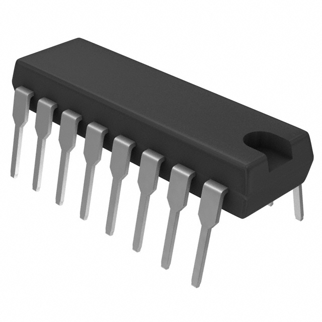
The INA103KP is a single-channel instrumentation amplifier manufactured by Texas Instruments in a 16-PDIP through-hole package. This device is designed for precision signal conditioning applications requiring high input impedance and low offset voltage characteristics. The INA103KP maintains active product status with 1202 units in current inventory. Equivalent and substitute parts are identified to support design flexibility, supply chain alternatives, and application-specific requirements where performance parameters align with the original specification.
Substiute Parts
Key Parameters
| Parameter | Value | Unit |
|---|---|---|
| Amplifier Type | Instrumentation | — |
| Number of Circuits | 1 | — |
| Slew Rate | 15 | V/µs |
| -3dB Bandwidth | 6 | MHz |
| Current - Input Bias | 2.5 | µA |
| Voltage - Input Offset | 30 | µV |
| Current - Supply | 9 | mA |
| Current - Output / Channel | 40 | mA |
| Voltage - Supply Span (Min) | 18 | V |
| Voltage - Supply Span (Max) | 50 | V |
| Operating Temperature | 0 to 70 | °C |
| Package / Case | 16-DIP (0.300", 7.62mm) | — |
| Mounting Type | Through Hole | — |
Substitute Part Grouping Explanation
Substitute parts for the INA103KP are identified based on functional equivalence within the linear amplifier category. The primary substitution criterion is the ability to perform single-channel amplification with compatible electrical performance in precision signal conditioning applications.
The AD8220TRMZ-EP from Analog Devices Inc. is listed as a manufacturer-recommended substitute. Substitution compatibility is determined by the following parameters:
- Single amplifier circuit configuration
- Active product status and current manufacturing
- RoHS3 compliance and REACH unaffected status
- ECCN and HTSUS classification alignment
- Functional capability in instrumentation and precision amplification roles
Differences in package type (16-PDIP through-hole versus 8-MSOP surface mount), amplifier topology (instrumentation versus J-FET), and electrical specifications require application-level evaluation to confirm suitability for specific circuit implementations.
Parameter Comparison
| Parameter | INA103KP | AD8220TRMZ-EP | Unit |
|---|---|---|---|
| Manufacturer | Texas Instruments | Analog Devices Inc. | — |
| Amplifier Type | Instrumentation | J-FET | — |
| Number of Circuits | 1 | 1 | — |
| Slew Rate | 15 | 2 | V/µs |
| -3dB Bandwidth | 6 | 1.5 | MHz |
| Current - Supply | 9 | 0.75 | mA |
| Current - Output / Channel | 40 | 15 | mA |
| Voltage - Supply Span (Min) | 18 | 4.5 | V |
| Voltage - Supply Span (Max) | 50 | 36 | V |
| Operating Temperature | 0 to 70 | -55 to 125 | °C |
| Mounting Type | Through Hole | Surface Mount | — |
| Package / Case | 16-DIP (0.300", 7.62mm) | 8-TSSOP, 8-MSOP (0.118", 3.00mm) | — |
| Product Status | Active | Active | — |
| RoHS Status | ROHS3 Compliant | ROHS3 Compliant | — |
| REACH Status | REACH Unaffected | REACH Unaffected | — |
Engineering Selection Recommendations
Both the INA103KP and AD8220TRMZ-EP maintain active product status with current manufacturing support. Both devices are RoHS3 compliant and REACH unaffected, meeting regulatory requirements for industrial and commercial applications.
The INA103KP is suitable for applications requiring through-hole mounting, higher slew rate performance (15 V/µs), extended bandwidth (6 MHz), and higher output current capability (40 mA per channel). Supply voltage requirements range from 18 V to 50 V.
The AD8220TRMZ-EP is suitable for applications requiring surface-mount integration, lower power consumption (0.75 mA supply current), extended operating temperature range (-55°C to 125°C), and flexible supply voltage operation (4.5 V to 36 V). This device incorporates rail-to-rail output capability and J-FET input architecture.
Selection between these devices depends on circuit board assembly method, power budget constraints, thermal operating environment, and supply voltage availability in the target application.
Frequently Asked Questions (FAQ)
Q: Can the AD8220TRMZ-EP directly replace the INA103KP in an existing PCB design?
A: Direct replacement is not possible without circuit board redesign. The INA103KP uses through-hole 16-DIP packaging, while the AD8220TRMZ-EP uses surface-mount 8-MSOP packaging. Pin configurations and footprints are incompatible. Additionally, the amplifier topologies differ (instrumentation versus J-FET), requiring verification of circuit performance parameters.
Q: What are the key electrical differences between these devices?
A: The INA103KP provides higher slew rate (15 V/µs versus 2 V/µs), wider bandwidth (6 MHz versus 1.5 MHz), and higher output current (40 mA versus 15 mA). The AD8220TRMZ-EP offers lower supply current consumption (0.75 mA versus 9 mA), wider operating temperature range (-55°C to 125°C versus 0°C to 70°C), and lower minimum supply voltage (4.5 V versus 18 V).
Q: Are both devices suitable for precision instrumentation applications?
A: Both devices are designed for precision signal conditioning. The INA103KP is specifically classified as an instrumentation amplifier with 30 µV input offset voltage and 2.5 µA input bias current. The AD8220TRMZ-EP is a J-FET amplifier with rail-to-rail output. Application suitability depends on specific offset voltage, bias current, and bandwidth requirements of the target circuit.
Q: What compliance certifications apply to both parts?
A: Both the INA103KP and AD8220TRMZ-EP are RoHS3 compliant and REACH unaffected. Both are classified under ECCN EAR99 and HTSUS 8542.33.0001. These certifications support use in regulated industrial, medical, and commercial applications.
Q: Which device is better for low-power applications?
A: The AD8220TRMZ-EP is better suited for low-power applications, consuming 0.75 mA supply current compared to 9 mA for the INA103KP. The AD8220TRMZ-EP also supports lower minimum supply voltage (4.5 V), enabling operation from single-cell battery sources and low-voltage power supplies.
Q: Can these devices be used interchangeably in new designs?
A: These devices are not interchangeable without application-specific evaluation. While both are single-channel amplifiers with active product status, differences in amplifier type, electrical performance, package style, and operating specifications require circuit design verification. Selection should be based on specific application requirements for bandwidth, slew rate, power consumption, temperature range, and supply voltage.
Alternative Parts

SJ6012L2TP
Littelfuse Inc.
6 Alternative Parts

JMK107BBJ476MA-RE
Taiyo Yuden
10 Alternative Parts

GMK107BBJ475MA-T
Taiyo Yuden
5 Alternative Parts
SJ6020N2ARP
Littelfuse Inc.
3 Alternative Parts
SJ6025R2ATP
Littelfuse Inc.
4 Alternative Parts

2474-05L
API Delevan Inc.
1 Alternative Parts

4590R-684K
API Delevan Inc.
1 Alternative Parts

CM6560R-334
API Delevan Inc.
1 Alternative Parts

CM6460-104
API Delevan Inc.
1 Alternative Parts

5526-12
API Delevan Inc.
1 Alternative Parts