


Request Quote
(Ships tomorrow)
HRF3205 N-Channel MOSFET Equivalent & Substitute Parts
Part Overview
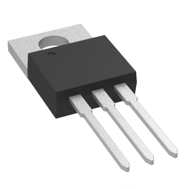
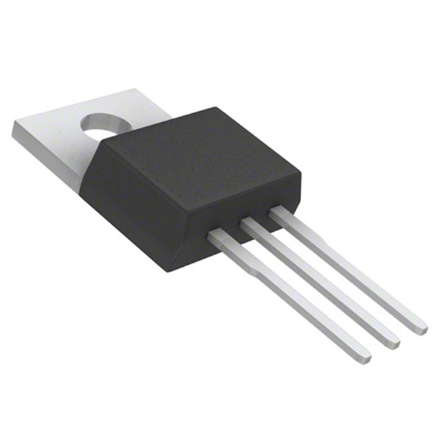
The HRF3205 is an N-Channel MOSFET manufactured by onsemi, rated for 55V drain-to-source voltage with 100A continuous drain current at 25°C (Tc) and 175W maximum power dissipation. The device is packaged in TO-220-3 through-hole configuration and operates across the temperature range of -55°C to 175°C (TJ).
The HRF3205 is classified as obsolete. Equivalent and substitute parts are necessary to maintain design continuity, ensure supply chain availability, and support ongoing production requirements for applications utilizing this MOSFET specification.
Substiute Parts
Key Parameters
| Parameter | HRF3205 Value | Unit |
|---|---|---|
| FET Type | N-Channel | — |
| Technology | MOSFET (Metal Oxide) | — |
| Drain to Source Voltage (Vdss) | 55 | V |
| Current - Continuous Drain (Id) @ 25°C | 100 | A (Tc) |
| Rds On (Max) @ Id, Vgs | 8 | mOhm @ 59A, 10V |
| Gate Charge (Qg) (Max) @ Vgs | 170 | nC @ 10V |
| Power Dissipation (Max) | 175 | W (Tc) |
| Operating Temperature | -55 to 175 | °C (TJ) |
| Mounting Type | Through Hole | — |
| Package / Case | TO-220-3 | — |
Substitute Part Grouping Explanation
Substitution of the HRF3205 is determined by the following critical parameters:
Voltage Rating (Vdss): The substitute must equal or exceed 55V to maintain voltage margin in the application circuit.
Continuous Drain Current (Id @ 25°C): The substitute must support 100A (Tc) or higher to ensure adequate current handling capacity.
On-State Resistance (Rds On): The substitute should maintain comparable or lower on-state resistance to preserve thermal performance and minimize power loss.
Gate Charge (Qg): Lower gate charge values reduce switching losses and improve gate drive efficiency.
Power Dissipation (Max): The substitute must support thermal requirements equivalent to or exceeding 175W (Tc).
Package and Mounting: All substitutes must be through-hole TO-220-3 configuration to ensure mechanical and electrical compatibility with existing PCB layouts.
Operating Temperature Range: The substitute must support the full -55°C to 175°C (TJ) operating range.
Substitutes are grouped into three categories based on voltage and current ratings:
Category A (55V, 100A+): Direct replacements matching or exceeding the HRF3205 specification.
Category B (60V, 75A–100A): Higher voltage rating with comparable or slightly reduced current ratings, suitable for applications with voltage margin requirements.
Category C (75V, 100A+): Elevated voltage rating for applications requiring additional voltage headroom.
Parameter Comparison
| Part Number | Manufacturer | Vdss (V) | Id @ 25°C (A) | Rds On (mOhm) | Qg (nC) | Pd Max (W) | Package | Status |
|---|---|---|---|---|---|---|---|---|
| HRF3205 | onsemi | 55 | 100 (Tc) | 8 @ 59A, 10V | 170 @ 10V | 175 (Tc) | TO-220-3 | Obsolete |
| AOT2610L | Alpha & Omega Semiconductor Inc. | 60 | 55 (Tc) | 10.7 @ 20A, 10V | 30 @ 10V | 75 (Tc) | TO-220-3 | Active |
| AOT470 | Alpha & Omega Semiconductor Inc. | 75 | 100 (Tc) | 10.5 @ 30A, 10V | 136 @ 10V | 268 (Tc) | TO-220-3 | Active |
| CSD18534KCS | Texas Instruments | 60 | 100 (Tc) | 9.5 @ 40A, 10V | 24 @ 10V | 107 (Tc) | TO-220-3 | Active |
| IRF1010EPBF | Infineon Technologies | 60 | 84 (Tc) | 12 @ 50A, 10V | 130 @ 10V | 200 (Tc) | TO-220-3 | Not For New Designs |
| IRF1010EZPBF | Infineon Technologies | 60 | 75 (Tc) | 8.5 @ 51A, 10V | 86 @ 10V | 140 (Tc) | TO-220-3 | Active |
| IRF1010NPBF | Infineon Technologies | 55 | 85 (Tc) | 11 @ 43A, 10V | 120 @ 10V | 180 (Tc) | TO-220-3 | Not For New Designs |
| IRF1405PBF | Infineon Technologies | 55 | 169 (Tc) | 5.3 @ 101A, 10V | 260 @ 10V | 330 (Tc) | TO-220-3 | Active |
| IRF3205PBF | Infineon Technologies | 55 | 110 (Tc) | 8 @ 62A, 10V | 146 @ 10V | 200 (Tc) | TO-220-3 | Active |
| IRFZ44ZPBF | Infineon Technologies | 55 | 51 (Tc) | 13.9 @ 31A, 10V | 43 @ 10V | 80 (Tc) | TO-220-3 | Not For New Designs |
| IRFZ46NPBF | Infineon Technologies | 55 | 53 (Tc) | 16.5 @ 28A, 10V | 72 @ 10V | 107 (Tc) | TO-220-3 | Not For New Designs |
Engineering Selection Recommendations
Primary Recommendation: IRF3205PBF
The IRF3205PBF from Infineon Technologies is the optimal substitute for the HRF3205. It matches the 55V voltage rating and exceeds the 100A continuous drain current specification with 110A (Tc). The on-state resistance of 8 mOhm at 62A, 10V is equivalent to the HRF3205. Power dissipation capability of 200W (Tc) exceeds the original specification. The device is classified as Active, ensuring long-term availability and supply chain continuity. RoHS3 compliance and REACH Unaffected status confirm regulatory alignment.
Secondary Recommendation: CSD18534KCS
The CSD18534KCS from Texas Instruments (NexFET™ series) provides a 60V voltage rating with 100A (Tc) continuous drain current, matching the HRF3205 current specification. The on-state resistance of 9.5 mOhm at 40A, 10V is comparable. Gate charge of 24 nC at 10V is significantly lower than the HRF3205, reducing switching losses. The device is Active and RoHS3 compliant. The elevated voltage rating provides additional margin for applications with transient voltage spikes.
Tertiary Recommendation: AOT470
The AOT470 from Alpha & Omega Semiconductor Inc. offers a 75V voltage rating with 100A (Tc) continuous drain current. Power dissipation of 268W (Tc) substantially exceeds the HRF3205 specification. The device is Active and RoHS3 compliant. This option is suitable for applications requiring elevated voltage headroom and thermal margin.
Not Recommended for New Designs:
IRF1010EPBF, IRF1010NPBF, IRFZ44ZPBF, and IRFZ46NPBF are classified as Not For New Designs. While these devices may provide functional substitution in legacy applications, they are not suitable for new product development due to obsolescence trajectory.
Voltage Consideration:
Substitutes with 60V or 75V ratings are electrically compatible with 55V applications. The elevated voltage rating does not degrade performance and provides additional transient voltage protection. No circuit modification is required.
Frequently Asked Questions (FAQ)
Q: Can the CSD18534KCS replace the HRF3205 in a 55V application?
A: Yes. The CSD18534KCS is rated for 60V, which exceeds the 55V requirement of the HRF3205. The higher voltage rating provides additional margin and does not require circuit modification. The 100A (Tc) current rating matches the HRF3205 specification.
Q: What is the significance of gate charge (Qg) differences between substitutes?
A: Gate charge determines the energy required to switch the MOSFET on and off. Lower gate charge values reduce switching losses and improve gate driver efficiency. The CSD18534KCS has 24 nC gate charge compared to the HRF3205's 170 nC, resulting in lower switching losses and reduced thermal stress on the gate driver circuit.
Q: Is the AOT470 suitable for applications requiring the exact 55V rating of the HRF3205?
A: Yes. The AOT470 is rated for 75V, which is compatible with 55V applications. The higher voltage rating does not degrade performance in 55V circuits. The 100A (Tc) current rating and 268W (Tc) power dissipation exceed the HRF3205 specification, providing additional thermal margin.
Q: Why are some substitutes classified as "Not For New Designs"?
A: Devices classified as Not For New Designs are in the final stages of product lifecycle. While they may provide functional substitution in existing applications, manufacturers do not recommend their use in new product development due to potential future discontinuation. For new designs, select from Active status devices such as IRF3205PBF, CSD18534KCS, or AOT470.
Q: Are all substitute parts compatible with the TO-220-3 PCB footprint of the HRF3205?
A: Yes. All substitute parts listed are packaged in TO-220-3 through-hole configuration, ensuring mechanical and electrical compatibility with existing PCB layouts. No PCB redesign is required for substitution.
Q: What is the difference between Rds On specifications at different current levels?
A: On-state resistance (Rds On) varies with gate-source voltage (Vgs) and drain current (Id). The HRF3205 specifies 8 mOhm at 59A and 10V. Substitutes may specify Rds On at different current levels. Lower Rds On values reduce conduction losses and heat generation. When comparing substitutes, prioritize devices with Rds On values at or below the HRF3205 specification to maintain thermal performance.
Q: Can the IRF1010EZPBF be used as a substitute despite its lower 75A (Tc) rating compared to the HRF3205's 100A (Tc)?
A: The IRF1010EZPBF is not recommended as a primary substitute due to its reduced current rating of 75A (Tc). If the application requires the full 100A capability of the HRF3205, the IRF1010EZPBF will not provide adequate current margin. However, for applications with actual current requirements below 75A, the IRF1010EZPBF may be acceptable. Verify application current requirements before selection.
Q: What compliance certifications should be verified for substitute parts?
A: All listed substitute parts are RoHS3 compliant and REACH Unaffected, matching the regulatory status of the HRF3205. Verify that selected substitutes meet the specific compliance requirements of your application and target markets before final selection.
Alternative Parts

SJ6012L2TP
Littelfuse Inc.
6 Alternative Parts

JMK107BBJ476MA-RE
Taiyo Yuden
10 Alternative Parts

GMK107BBJ475MA-T
Taiyo Yuden
5 Alternative Parts
SJ6020N2ARP
Littelfuse Inc.
3 Alternative Parts
SJ6025R2ATP
Littelfuse Inc.
4 Alternative Parts

2474-05L
API Delevan Inc.
1 Alternative Parts

4590R-684K
API Delevan Inc.
1 Alternative Parts

CM6560R-334
API Delevan Inc.
1 Alternative Parts

CM6460-104
API Delevan Inc.
1 Alternative Parts

5526-12
API Delevan Inc.
1 Alternative Parts