


Request Quote
(Ships tomorrow)
GT080N10M Equivalent & Substitute Parts
Part Overview
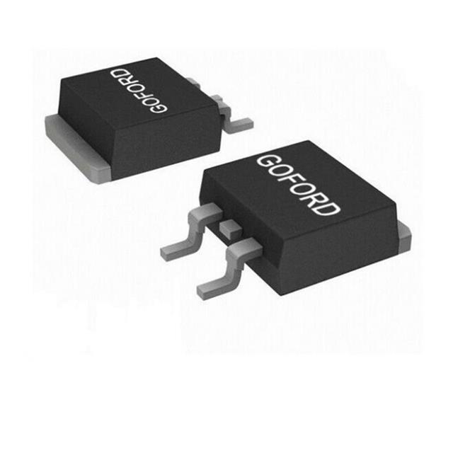
The GT080N10M is an N-Channel MOSFET manufactured by Goford Semiconductor, classified within the SGT series. This device operates at 100V drain-to-source voltage with a continuous drain current rating of 70A at 25°C and dissipates up to 100W. The component is housed in a TO-263 surface mount package and is currently in active production status with 1,669 units available in stock. The GT080N10M serves as a switching element in power conversion circuits, motor control applications, and high-current DC switching topologies where the specified voltage and current ratings are required.
Substiute Parts
Key Parameters
| Parameter | Value | Unit |
|---|---|---|
| Drain to Source Voltage (Vdss) | 100 | V |
| Continuous Drain Current (Id) @ 25°C | 70 | A (Tc) |
| Rds On (Max) @ 20A, 10V | 7.5 | mOhm |
| Gate Threshold Voltage (Vgs(th)) @ 250µA | 3 | V (Max) |
| Power Dissipation (Max) | 100 | W (Tc) |
| Gate Charge (Qg) @ 10V | 35 | nC (Max) |
| Input Capacitance (Ciss) @ 50V | 2125 | pF (Max) |
| Operating Temperature Range | -55 to 150 | °C (TJ) |
| Package Type | TO-263-3, D2PAK | Surface Mount |
| FET Type | N-Channel | |
| Technology | MOSFET (Metal Oxide) |
Substitute Part Grouping Explanation
Substitution eligibility for the GT080N10M is determined by strict equivalence across the following critical electrical and mechanical parameters:
Electrical Criteria:
- Drain to Source Voltage (Vdss): 100V minimum
- Continuous Drain Current (Id) @ 25°C: 70A minimum
- On-State Resistance (Rds On) @ 20A, 10V: 7.5 mOhm maximum
- Gate Threshold Voltage (Vgs(th)): 3V maximum at 250µA
- Power Dissipation: 100W minimum
- Gate Charge (Qg) @ 10V: 35 nC maximum
- Input Capacitance (Ciss) @ 50V: 2125 pF maximum
Mechanical Criteria:
- Package Type: TO-263-3 / D2PAK surface mount configuration
- Mounting Type: Surface mount
- Lead configuration: 2 Leads + Tab
Compliance Criteria:
- RoHS Compliant status
- REACH Unaffected classification
- Active product status
Parts meeting all specified parameters within the stated tolerances are classified as direct parametric equivalents. The GT080N10M itself represents the baseline specification for this substitution group.
Parameter Comparison
| Parameter | GT080N10M (Main Part) | GT080N10M (Substitute) | Match Status |
|---|---|---|---|
| Manufacturer | Goford Semiconductor | Goford Semiconductor | Identical |
| Series | SGT | SGT | Identical |
| FET Type | N-Channel | N-Channel | Identical |
| Technology | MOSFET (Metal Oxide) | MOSFET (Metal Oxide) | Identical |
| Vdss | 100 V | 100 V | Identical |
| Id @ 25°C | 70 A (Tc) | 70 A (Tc) | Identical |
| Rds On (Max) @ 20A, 10V | 7.5 mOhm | 7.5 mOhm | Identical |
| Vgs(th) (Max) @ 250µA | 3 V | 3 V | Identical |
| Qg (Max) @ 10V | 35 nC | 35 nC | Identical |
| Ciss (Max) @ 50V | 2125 pF | 2125 pF | Identical |
| Power Dissipation (Max) | 100 W (Tc) | 100 W (Tc) | Identical |
| Operating Temperature | -55 to 150 °C (TJ) | -55 to 150 °C (TJ) | Identical |
| Package / Case | TO-263-3, D2PAK | TO-263-3, D2PAK | Identical |
| Mounting Type | Surface Mount | Surface Mount | Identical |
| RoHS Status | RoHS Compliant | RoHS Compliant | Identical |
| REACH Status | REACH Unaffected | REACH Unaffected | Identical |
Engineering Selection Recommendations
The GT080N10M is the sole part identified within the provided substitute list. This part maintains active product status with confirmed inventory availability of 1,669 units in new original condition. The device carries full RoHS compliance certification and REACH unaffected classification, satisfying regulatory requirements for industrial and commercial applications.
Selection of the GT080N10M is appropriate for applications requiring:
- 100V maximum drain-to-source voltage operation
- 70A continuous drain current at 25°C ambient
- Low on-state resistance of 7.5 mOhm at specified gate drive conditions
- Surface mount integration in TO-263 package footprint
- Operating environments spanning -55°C to 150°C junction temperature range
The part's active status and substantial inventory position support both immediate procurement and long-term supply chain planning.
Frequently Asked Questions (FAQ)
Q: What electrical parameters define substitution compatibility for the GT080N10M?
A: Direct substitution requires matching all critical electrical specifications: 100V Vdss, 70A continuous drain current at 25°C, 7.5 mOhm maximum Rds On at 20A and 10V gate drive, 3V maximum gate threshold voltage, 35 nC maximum gate charge at 10V, and 2125 pF maximum input capacitance at 50V. Deviations from any specified parameter disqualify a part from direct substitution.
Q: Is the GT080N10M available in alternative package configurations?
A: The GT080N10M is specified exclusively in the TO-263-3 surface mount package, also designated as D2PAK with 2 leads plus tab configuration. No alternative package options are provided within the available data.
Q: What compliance certifications apply to the GT080N10M?
A: The GT080N10M carries RoHS Compliant status and REACH Unaffected classification. The part is assigned ECCN code EAR99 and HTSUS code 8541.29.0095 for export and tariff purposes.
Q: Can the GT080N10M be used in applications requiring higher current ratings?
A: The GT080N10M is rated for 70A continuous drain current at 25°C. Applications requiring higher current capacity require selection of alternative parts with higher Id ratings. The specified 70A rating represents the maximum continuous current for this device.
Q: What is the thermal operating range for the GT080N10M?
A: The GT080N10M operates across a junction temperature range of -55°C to 150°C. Thermal management design must ensure junction temperature remains within this specified range during all operating conditions.
Q: How does gate charge affect circuit design with the GT080N10M?
A: The GT080N10M exhibits 35 nC maximum gate charge at 10V. This parameter influences gate driver selection and switching speed characteristics. Higher gate charge requires proportionally higher gate current for equivalent switching frequency performance.
Q: What is the significance of the 7.5 mOhm on-state resistance specification?
A: The 7.5 mOhm Rds On specification is measured at 20A drain current and 10V gate-source voltage. This parameter directly determines conduction losses and thermal dissipation. Lower Rds On values reduce power loss and heat generation during on-state operation.
Alternative Parts

SJ6012L2TP
Littelfuse Inc.
6 Alternative Parts

JMK107BBJ476MA-RE
Taiyo Yuden
10 Alternative Parts

GMK107BBJ475MA-T
Taiyo Yuden
5 Alternative Parts
SJ6020N2ARP
Littelfuse Inc.
3 Alternative Parts
SJ6025R2ATP
Littelfuse Inc.
4 Alternative Parts

2474-05L
API Delevan Inc.
1 Alternative Parts

4590R-684K
API Delevan Inc.
1 Alternative Parts

CM6560R-334
API Delevan Inc.
1 Alternative Parts

CM6460-104
API Delevan Inc.
1 Alternative Parts

5526-12
API Delevan Inc.
1 Alternative Parts