


Request Quote
(Ships tomorrow)
FQPF30N06 Equivalent & Substitute Parts
Part Overview
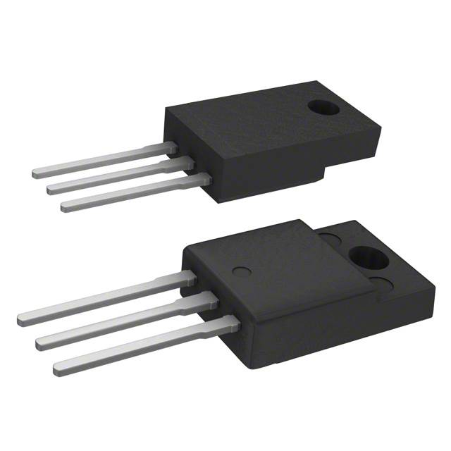
The FQPF30N06 is an N-Channel MOSFET manufactured by onsemi, rated for 60V drain-to-source voltage and 21A continuous drain current in a Through Hole TO-220F-3 package. This device is classified as obsolete, necessitating identification of equivalent and substitute components for ongoing design support and procurement requirements. The QFET® series device delivers 39W maximum power dissipation and operates across the temperature range of -55°C to 175°C.
Substiute Parts
Key Parameters
| Parameter | Value | Unit |
|---|---|---|
| FET Type | N-Channel | — |
| Drain to Source Voltage (Vdss) | 60 | V |
| Current - Continuous Drain (Id) @ 25°C | 21 | A |
| Rds On (Max) @ Id, Vgs | 40 | mOhm @ 10.5A, 10V |
| Vgs(th) (Max) @ Id | 4 | V @ 250µA |
| Gate Charge (Qg) (Max) @ Vgs | 25 | nC @ 10V |
| Vgs (Max) | ±25 | V |
| Input Capacitance (Ciss) (Max) @ Vds | 945 | pF @ 25V |
| Power Dissipation (Max) | 39 | W |
| Operating Temperature | -55 to 175 | °C |
| Mounting Type | Through Hole | — |
| Package / Case | TO-220-3 Full Pack | — |
| Technology | MOSFET (Metal Oxide) | — |
Substitute Part Grouping Explanation
Substitution of the FQPF30N06 is determined by electrical and mechanical compatibility across the following critical parameters:
Electrical Compatibility Criteria:
- Drain to Source Voltage (Vdss) must equal or exceed 60V
- Continuous Drain Current (Id) must meet or exceed 21A at 25°C
- Gate Threshold Voltage (Vgs(th)) must be compatible with 4V @ 250µA specification
- Maximum Gate Voltage (Vgs) must accommodate ±25V operation
- Operating temperature range must span -55°C to 175°C
Mechanical Compatibility Criteria:
- Mounting type must be Through Hole
- Package must be compatible with TO-220 form factor (TO-220-3, TO-220F-3, or TO-220FP)
Compliance Criteria:
- REACH Status: REACH Unaffected
- ECCN: EAR99
The substitute parts listed below satisfy these criteria and are therefore electrically and mechanically interchangeable within the specified operating parameters.
Parameter Comparison
| Parameter | FQPF30N06 | FQP30N06 | STF40NF06 |
|---|---|---|---|
| Manufacturer | onsemi | onsemi | STMicroelectronics |
| FET Type | N-Channel | N-Channel | N-Channel |
| Vdss | 60V | 60V | 60V |
| Id @ 25°C | 21A | 30A | 23A |
| Rds On (Max) @ Vgs 10V | 40 mOhm @ 10.5A | 40 mOhm @ 15A | 28 mOhm @ 11.5A |
| Vgs(th) (Max) @ Id | 4V @ 250µA | 4V @ 250µA | 4V @ 250µA |
| Gate Charge (Qg) (Max) @ 10V | 25 nC | 25 nC | 32 nC |
| Vgs (Max) | ±25V | ±25V | ±20V |
| Ciss (Max) @ 25V | 945 pF | 945 pF | 920 pF |
| Power Dissipation (Max) | 39W | 79W | 30W |
| Operating Temperature | -55 to 175°C | -55 to 175°C | -55 to 175°C |
| Mounting Type | Through Hole | Through Hole | Through Hole |
| Package / Case | TO-220-3 Full Pack | TO-220-3 | TO-220-3 Full Pack |
| Product Status | Obsolete | Obsolete | Obsolete |
| REACH Status | REACH Unaffected | REACH Unaffected | REACH Unaffected |
Engineering Selection Recommendations
FQP30N06 (onsemi): This substitute provides superior current handling capability at 30A continuous drain current, exceeding the FQPF30N06 requirement of 21A. The device maintains identical Vdss (60V), Vgs(th) (4V @ 250µA), and gate charge (25 nC @ 10V) specifications. Power dissipation capability is increased to 79W, providing additional thermal margin. The FQP30N06 is ROHS3 compliant and REACH unaffected. This part is suitable for direct substitution in applications where the increased current rating and power dissipation do not create thermal or layout constraints.
STF40NF06 (STMicroelectronics): This substitute from the STripFET™ II series delivers 23A continuous drain current, closely matching the FQPF30N06 specification of 21A. The device features improved on-resistance performance at 28 mOhm @ 11.5A, 10V compared to the original 40 mOhm @ 10.5A, 10V. Operating temperature range, Vdss (60V), and Vgs(th) (4V @ 250µA) are identical. The maximum gate voltage is ±20V, which is within the ±25V tolerance of the original device. Input capacitance is comparable at 920 pF @ 25V. The STF40NF06 is ROHS3 compliant and REACH unaffected. This part is suitable for direct substitution where the lower on-resistance and improved thermal characteristics are beneficial.
Both substitute parts are classified as obsolete, consistent with the original FQPF30N06 status. Selection between FQP30N06 and STF40NF06 depends on application-specific requirements for current capacity, on-resistance, and thermal performance.
Frequently Asked Questions (FAQ)
Q: Can the FQP30N06 be used as a direct replacement for the FQPF30N06?
A: Yes. The FQP30N06 meets all electrical compatibility criteria: 60V Vdss, 30A continuous drain current (exceeding the 21A requirement), identical gate threshold voltage (4V @ 250µA), and compatible operating temperature range (-55°C to 175°C). Both devices use Through Hole mounting in TO-220-3 package form factors. The increased current rating and power dissipation (79W vs. 39W) provide additional design margin.
Q: What is the difference between the TO-220F-3 and TO-220-3 packages?
A: The FQPF30N06 uses TO-220F-3 (Full Pack), while the FQP30N06 uses TO-220-3 standard package. Both are Through Hole TO-220 form factors with three leads (Gate, Drain, Source). The "Full Pack" designation indicates additional insulation or mechanical features. Pin configuration and electrical performance are compatible for circuit board layout purposes.
Q: Is the STF40NF06 suitable for high-frequency switching applications?
A: The STF40NF06 exhibits gate charge of 32 nC @ 10V, compared to 25 nC for the FQPF30N06. This 28% increase in gate charge results in slightly longer switching times. For applications sensitive to switching frequency or gate drive requirements, the FQP30N06 with identical 25 nC gate charge may be preferred.
Q: What is the significance of the on-resistance (Rds On) difference between these parts?
A: The FQPF30N06 and FQP30N06 both specify 40 mOhm maximum on-resistance at 10V gate voltage. The STF40NF06 provides superior performance at 28 mOhm @ 11.5A, 10V. Lower on-resistance reduces conduction losses and heat generation. For power-sensitive applications, the STF40NF06 offers improved efficiency.
Q: Are all three parts compliant with current environmental regulations?
A: Yes. All three parts (FQPF30N06, FQP30N06, and STF40NF06) are REACH unaffected and carry EAR99 ECCN classification. The FQP30N06 and STF40NF06 are ROHS3 compliant. The FQPF30N06 does not specify RoHS status but is REACH unaffected.
Q: Can these parts be used interchangeably in existing PCB designs?
A: The FQPF30N06 and FQP30N06 are directly interchangeable from an electrical standpoint. Both use TO-220-3 form factor packages with identical pin configuration. The STF40NF06 also uses TO-220-3 form factor and is pin-compatible. Physical board layout and thermal management considerations should be evaluated, particularly if upgrading to higher current-rated devices.
Q: What is the maximum gate voltage tolerance for each part?
A: The FQPF30N06 and FQP30N06 both specify ±25V maximum gate voltage. The STF40NF06 specifies ±20V maximum gate voltage. For applications requiring gate voltage excursions beyond ±20V, the onsemi parts (FQPF30N06 or FQP30N06) are required.
Alternative Parts

SJ6012L2TP
Littelfuse Inc.
6 Alternative Parts

JMK107BBJ476MA-RE
Taiyo Yuden
10 Alternative Parts

GMK107BBJ475MA-T
Taiyo Yuden
5 Alternative Parts
SJ6020N2ARP
Littelfuse Inc.
3 Alternative Parts
SJ6025R2ATP
Littelfuse Inc.
4 Alternative Parts

2474-05L
API Delevan Inc.
1 Alternative Parts

4590R-684K
API Delevan Inc.
1 Alternative Parts

CM6560R-334
API Delevan Inc.
1 Alternative Parts

CM6460-104
API Delevan Inc.
1 Alternative Parts

5526-12
API Delevan Inc.
1 Alternative Parts