


Request Quote
(Ships tomorrow)
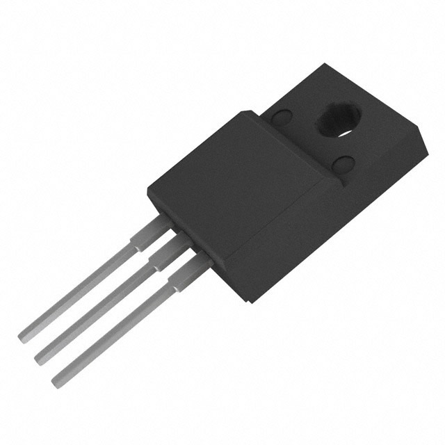
FQAF8N80 N-Channel MOSFET 800V 5.9A Equivalent & Substitute Parts
Part Overview
The FQAF8N80 is an N-Channel MOSFET manufactured by onsemi, rated for 800V drain-to-source voltage with a continuous drain current of 5.9A at 25°C. This device is housed in a TO-3PF through-hole package and is part of the QFET® series. The FQAF8N80 is classified as obsolete, making identification of equivalent and substitute parts essential for ongoing design support, maintenance, and production continuity. Substitute parts must maintain electrical compatibility across critical parameters including voltage rating, current capacity, and thermal characteristics while accommodating potential package differences.
Substiute Parts
Key Parameters
| Parameter | Value | Unit |
|---|---|---|
| Drain to Source Voltage (Vdss) | 800 | V |
| Continuous Drain Current (Id) @ 25°C | 5.9 | A (Tc) |
| On-State Resistance (Rds On Max) @ Id, Vgs | 1.2 | Ω @ 2.95A, 10V |
| Gate Threshold Voltage (Vgs(th) Max) @ Id | 5 | V @ 250µA |
| Power Dissipation (Max) | 107 | W (Tc) |
| Operating Temperature Range | -55 to 150 | °C (TJ) |
| Package Type | TO-3PF | Through Hole |
| FET Type | N-Channel | — |
| Technology | MOSFET (Metal Oxide) | — |
Substitute Part Grouping Explanation
Substitute parts for the FQAF8N80 are identified based on strict electrical and mechanical compatibility criteria. The primary substitution logic is based on the following parameters:
Critical Matching Parameters:
- Drain to Source Voltage (Vdss): Must equal or exceed 800V
- FET Type: Must be N-Channel
- Technology: Must be MOSFET (Metal Oxide)
- Operating Temperature Range: Must support -55°C to 150°C (TJ)
- On-State Resistance (Rds On): Must be compatible at specified gate voltage and current conditions
- Continuous Drain Current (Id): Must meet or exceed 5.9A at 25°C
Package Considerations: Substitute parts may utilize different through-hole packages (TO-247AC versus TO-3PF) provided the electrical specifications remain within acceptable parameters. Package differences require mechanical verification for board layout compatibility but do not affect electrical substitution validity.
The IRFPE50PBF meets all critical electrical parameters and operates within the same temperature range, making it a valid substitute despite package and manufacturer differences.
Parameter Comparison
| Parameter | FQAF8N80 (onsemi) | IRFPE50PBF (Vishay Siliconix) | Unit |
|---|---|---|---|
| Drain to Source Voltage (Vdss) | 800 | 800 | V |
| Continuous Drain Current (Id) @ 25°C | 5.9 | 7.8 | A (Tc) |
| On-State Resistance (Rds On Max) @ Vgs 10V | 1.2 @ 2.95A | 1.2 @ 4.7A | Ω |
| Gate Threshold Voltage (Vgs(th) Max) @ 250µA | 5 | 4 | V |
| Power Dissipation (Max) | 107 | 190 | W (Tc) |
| Operating Temperature Range | -55 to 150 | -55 to 150 | °C (TJ) |
| Package Type | TO-3PF | TO-247AC | Through Hole |
| FET Type | N-Channel | N-Channel | — |
| Technology | MOSFET (Metal Oxide) | MOSFET (Metal Oxide) | — |
| Product Status | Obsolete | Active | — |
Engineering Selection Recommendations
IRFPE50PBF as Primary Substitute:
The IRFPE50PBF is a valid substitute for the FQAF8N80 based on electrical parameter compatibility. Both devices share identical drain-to-source voltage ratings (800V), equivalent on-state resistance characteristics (1.2Ω at 10V gate voltage), and identical operating temperature ranges (-55°C to 150°C). The IRFPE50PBF provides higher continuous drain current (7.8A versus 5.9A) and greater power dissipation capability (190W versus 107W), offering improved thermal headroom in applications.
Compliance and Availability:
The IRFPE50PBF holds Active product status with ROHS3 compliance and REACH Unaffected designation, ensuring long-term availability and regulatory alignment. The FQAF8N80, classified as Obsolete, presents supply chain risk and limited future availability. Both devices carry identical ECCN (EAR99) and HTSUS (8541.29.0095) classifications.
Package Transition Consideration:
The primary difference between these devices is the package format: FQAF8N80 uses TO-3PF while IRFPE50PBF uses TO-247AC. Both are through-hole packages with different pin configurations and thermal characteristics. Board layout redesign is required to accommodate the TO-247AC footprint. The TO-247AC package provides superior thermal performance through enhanced lead design, supporting the higher power dissipation rating.
Moisture Sensitivity:
Both devices carry MSL 1 (Unlimited) classification, indicating no moisture sensitivity constraints during storage or handling.
Frequently Asked Questions (FAQ)
Q: Can the IRFPE50PBF directly replace the FQAF8N80 without circuit modification?
A: Electrical substitution is valid based on voltage rating, current capacity, and on-state resistance compatibility. However, the different package formats (TO-3PF versus TO-247AC) require PCB layout modification. Pin-to-pin electrical connections remain compatible, but physical mounting and thermal interface design differ between packages.
Q: What are the key electrical parameters that determine substitution validity?
A: Substitution validity is determined by: (1) Drain-to-source voltage rating equal to or exceeding 800V, (2) Continuous drain current capacity meeting or exceeding 5.9A at 25°C, (3) On-state resistance compatibility at specified gate voltage and current conditions, (4) Operating temperature range supporting -55°C to 150°C, and (5) N-Channel MOSFET technology type.
Q: Does the higher current rating (7.8A) and power dissipation (190W) of the IRFPE50PBF create any compatibility issues?
A: No. Higher current and power ratings represent improved performance margins. The IRFPE50PBF operates within the same voltage and temperature specifications as the FQAF8N80, making it electrically compatible. The enhanced thermal capability reduces junction temperature in equivalent operating conditions.
Q: Are there thermal interface differences between the TO-3PF and TO-247AC packages?
A: Yes. The TO-247AC package features a larger copper lead frame and different mounting geometry compared to TO-3PF, resulting in different thermal resistance characteristics. The TO-247AC typically provides lower thermal resistance to PCB, supporting the higher power dissipation rating. Thermal design verification is required during package transition.
Q: What is the significance of the FQAF8N80 being classified as Obsolete?
A: Obsolete status indicates the manufacturer has discontinued production and support. This creates supply chain risk for long-term applications. The IRFPE50PBF, with Active status, ensures continued availability and manufacturer support for future production runs and design revisions.
Q: Are there any regulatory or compliance differences between these devices?
A: Both devices carry identical ECCN (EAR99) and HTSUS (8541.29.0095) classifications. The IRFPE50PBF includes ROHS3 compliance certification, while the FQAF8N80 does not specify RoHS status. Both are REACH Unaffected. Compliance verification against specific application requirements is recommended.
Q: Can the FQAF8N80 be used as a substitute for the IRFPE50PBF in new designs?
A: No. The FQAF8N80 is obsolete with limited inventory availability. New designs should utilize the IRFPE50PBF to ensure long-term supply chain continuity and manufacturer support.
Alternative Parts

SJ6012L2TP
Littelfuse Inc.
6 Alternative Parts

JMK107BBJ476MA-RE
Taiyo Yuden
10 Alternative Parts

GMK107BBJ475MA-T
Taiyo Yuden
5 Alternative Parts
SJ6020N2ARP
Littelfuse Inc.
3 Alternative Parts
SJ6025R2ATP
Littelfuse Inc.
4 Alternative Parts

2474-05L
API Delevan Inc.
1 Alternative Parts

4590R-684K
API Delevan Inc.
1 Alternative Parts

CM6560R-334
API Delevan Inc.
1 Alternative Parts

CM6460-104
API Delevan Inc.
1 Alternative Parts

5526-12
API Delevan Inc.
1 Alternative Parts