


Request Quote
(Ships tomorrow)
FLZ2V4B Equivalent & Substitute Parts
Part Overview
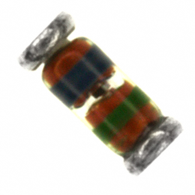
The FLZ2V4B is a Zener diode manufactured by onsemi, rated at 2.5 V nominal with 500 mW power dissipation in a surface mount SOD-80 (DO-213AC, MINI-MELF) package. This component is classified as obsolete, indicating that onsemi has discontinued production. Locating equivalent substitute parts is necessary to support ongoing design requirements, maintenance operations, and production continuity for applications utilizing this Zener diode specification.
Substiute Parts
Key Parameters
| Parameter | Value | Unit |
|---|---|---|
| Voltage - Zener (Nom) | 2.5 | V |
| Tolerance | ±4% | - |
| Power - Max | 500 | mW |
| Impedance (Max) | 35 | Ohms |
| Current - Reverse Leakage @ Vr | 84 | µA @ 1 V |
| Voltage - Forward (Vf) (Max) @ If | 1.2 | V @ 200 mA |
| Operating Temperature Range | -65 to 175 | °C |
| Mounting Type | Surface Mount | - |
| Package / Case | DO-213AC, MINI-MELF, SOD-80 | - |
| Moisture Sensitivity Level | 1 (Unlimited) | - |
Substitute Part Grouping Explanation
Substitute parts for the FLZ2V4B are qualified based on the following electrical and mechanical parameters:
Critical Matching Parameters:
- Zener voltage nominal rating: 2.5 V
- Maximum power dissipation: 500 mW
- Package type: SOD-80 (DO-213AC, MINI-MELF)
- Mounting configuration: Surface Mount
- Operating temperature range: -65°C to 175°C
Allowable Variations:
- Zener voltage tolerance: ±4% to ±5% (substitute tolerance of ±5% is acceptable for applications designed around ±4% specification)
- Impedance (Max): 30 to 35 Ohms (lower impedance values are acceptable)
- Reverse leakage current: 84 to 100 µA @ 1 V (minor variation acceptable within operational margins)
- Forward voltage: 1.1 to 1.2 V @ 200 mA (minor variation acceptable)
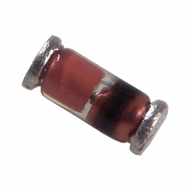
The substitute parts TZM5222B-GS08 and TZM5222B-GS18, both manufactured by Vishay General Semiconductor - Diodes Division, meet all critical electrical and mechanical requirements for direct substitution with the FLZ2V4B.
Parameter Comparison
| Parameter | FLZ2V4B (onsemi) | TZM5222B-GS08 (Vishay) | TZM5222B-GS18 (Vishay) |
|---|---|---|---|
| Voltage - Zener (Nom) | 2.5 V | 2.5 V | 2.5 V |
| Tolerance | ±4% | ±5% | ±5% |
| Power - Max | 500 mW | 500 mW | 500 mW |
| Impedance (Max) | 35 Ohms | 30 Ohms | 30 Ohms |
| Current - Reverse Leakage @ Vr | 84 µA @ 1 V | 100 µA @ 1 V | 100 µA @ 1 V |
| Voltage - Forward (Vf) (Max) @ If | 1.2 V @ 200 mA | 1.1 V @ 200 mA | 1.1 V @ 200 mA |
| Operating Temperature Range | -65°C to 175°C | -65°C to 175°C | -65°C to 175°C |
| Mounting Type | Surface Mount | Surface Mount | Surface Mount |
| Package / Case | DO-213AC, MINI-MELF, SOD-80 | DO-213AC, MINI-MELF, SOD-80 | DO-213AC, MINI-MELF, SOD-80 |
| Moisture Sensitivity Level | 1 (Unlimited) | 1 (Unlimited) | 1 (Unlimited) |
| Product Status | Obsolete | Active | Active |
| RoHS Status | REACH Unaffected | ROHS3 Compliant | ROHS3 Compliant |
Engineering Selection Recommendations
TZM5222B-GS08 (Vishay General Semiconductor - Diodes Division)
This substitute part is classified as Active product status with ROHS3 compliance. The TZM5222B-GS08 provides equivalent electrical performance with improved impedance characteristics (30 Ohms vs. 35 Ohms maximum). Current inventory availability is 27,600 pieces, supporting high-volume production requirements. The ±5% tolerance specification is compatible with circuit designs originally specified for the FLZ2V4B's ±4% tolerance.
TZM5222B-GS18 (Vishay General Semiconductor - Diodes Division)
This substitute part is also classified as Active product status with ROHS3 compliance and shares identical electrical specifications with the TZM5222B-GS08. The primary distinction is packaging configuration (Tape & Reel designation GS18 vs. GS08). Current inventory availability is 692 pieces. This option is suitable for applications where the specific tape reel configuration is required.
Both Vishay substitute parts satisfy all critical electrical parameters, mechanical compatibility, and regulatory compliance requirements for direct replacement of the obsolete FLZ2V4B component.
Frequently Asked Questions (FAQ)
Q: Can TZM5222B-GS08 or TZM5222B-GS18 be used as direct replacements for FLZ2V4B in existing designs?
A: Yes. Both Vishay parts meet the critical electrical specifications: 2.5 V nominal Zener voltage, 500 mW power rating, and SOD-80 surface mount package. The ±5% tolerance of the substitute parts is compatible with applications designed for the FLZ2V4B's ±4% tolerance specification.
Q: What is the difference between TZM5222B-GS08 and TZM5222B-GS18?
A: Both parts have identical electrical specifications. The difference is in packaging configuration: GS08 and GS18 designations refer to different tape and reel specifications for automated assembly. Selection depends on your production equipment requirements.
Q: Are the substitute parts RoHS compliant?
A: Yes. Both TZM5222B-GS08 and TZM5222B-GS18 are ROHS3 compliant. The original FLZ2V4B is REACH unaffected. All three parts are suitable for applications with RoHS compliance requirements.
Q: What is the impedance difference between FLZ2V4B and the substitute parts?
A: The FLZ2V4B has a maximum impedance of 35 Ohms, while both Vishay substitutes have a maximum impedance of 30 Ohms. Lower impedance provides improved voltage regulation characteristics and is acceptable for direct substitution.
Q: Are there inventory considerations for selecting between the two Vishay options?
A: TZM5222B-GS08 has 27,600 pieces in stock, while TZM5222B-GS18 has 692 pieces in stock. For high-volume production, TZM5222B-GS08 offers greater availability. For lower-volume applications, either part is suitable based on packaging requirements.
Q: Do the substitute parts operate across the same temperature range?
A: Yes. All three parts operate across the identical temperature range of -65°C to 175°C, ensuring thermal compatibility in all application environments.
Q: What is the forward voltage difference?
A: The FLZ2V4B has a maximum forward voltage of 1.2 V @ 200 mA, while both Vishay substitutes have 1.1 V @ 200 mA. The lower forward voltage of the substitutes represents improved performance characteristics.
Alternative Parts

SJ6012L2TP
Littelfuse Inc.
6 Alternative Parts

JMK107BBJ476MA-RE
Taiyo Yuden
10 Alternative Parts

GMK107BBJ475MA-T
Taiyo Yuden
5 Alternative Parts
SJ6020N2ARP
Littelfuse Inc.
3 Alternative Parts
SJ6025R2ATP
Littelfuse Inc.
4 Alternative Parts

2474-05L
API Delevan Inc.
1 Alternative Parts

4590R-684K
API Delevan Inc.
1 Alternative Parts

CM6560R-334
API Delevan Inc.
1 Alternative Parts

CM6460-104
API Delevan Inc.
1 Alternative Parts

5526-12
API Delevan Inc.
1 Alternative Parts