


Request Quote
(Ships tomorrow)
FEPB16FTHE3_A/P Equivalent & Substitute Parts
Part Overview
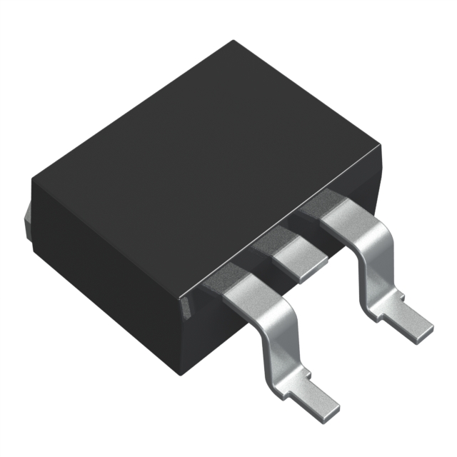
The FEPB16FTHE3_A/P is a general-purpose diode array manufactured by Vishay General Semiconductor - Diodes Division. This component features a 1 Pair Common Cathode configuration rated for 300 V DC reverse voltage and 8 A average rectified current per diode. The device is packaged in TO-263-3 (D2PAK) surface mount format with automotive-grade qualification (AEC-Q101).
This part is designated as Last Time Buy, indicating discontinued production status. Equivalent and substitute parts are necessary to maintain design continuity and ensure component availability for ongoing production and field support applications.
Substiute Parts
Key Parameters
| Parameter | Value |
|---|---|
| Diode Configuration | 1 Pair Common Cathode |
| Voltage - DC Reverse (Vr) (Max) | 300 V |
| Current - Average Rectified (Io) (per Diode) | 8 A |
| Voltage - Forward (Vf) (Max) @ If | 1.3 V @ 8 A |
| Speed | Fast Recovery ≤ 500ns, > 200mA (Io) |
| Reverse Recovery Time (trr) | 50 ns |
| Current - Reverse Leakage @ Vr | 10 µA @ 300 V |
| Operating Temperature - Junction | -55°C ~ 150°C |
| Package / Case | TO-263-3, D2PAK (2 Leads + Tab), TO-263AB |
| Grade | Automotive |
| Qualification | AEC-Q101 |
| RoHS Status | ROHS3 Compliant |
Substitute Part Grouping Explanation
Substitution of the FEPB16FTHE3_A/P is determined by the following critical parameters:
Mandatory Compatibility Criteria:
- Diode Configuration: 1 Pair Common Cathode (electrical pinout compatibility)
- Package / Case: TO-263-3, D2PAK (mechanical and thermal interface)
- Voltage - DC Reverse (Vr) (Max): 300 V minimum (circuit voltage rating)
- Current - Average Rectified (Io) (per Diode): 8 A minimum (load current capacity)
- Speed: Fast Recovery ≤ 500ns, > 200mA (Io) (switching performance)
- Mounting Type: Surface Mount (assembly process compatibility)
Acceptable Parameter Variations: Substitute parts may exceed the original specifications in voltage rating, current capacity, forward voltage, reverse recovery time, and operating temperature range without compromising circuit function. Lower specifications in these parameters are not acceptable.
The substitute parts listed below meet or exceed all mandatory compatibility criteria and maintain electrical and mechanical interchangeability with the FEPB16FTHE3_A/P.
Parameter Comparison
| Parameter | FEPB16FTHE3_A/P | FEPB16GTHM3/I | SBR40U300CTB | SBR40U300CTB-13 | STTH2003CGY-TR | STTH30R03CG-TR |
|---|---|---|---|---|---|---|
| Manufacturer | Vishay | Vishay | Diodes Inc. | Diodes Inc. | STMicroelectronics | STMicroelectronics |
| Diode Configuration | 1 Pair Common Cathode | 1 Pair Common Cathode | 1 Pair Common Cathode | 1 Pair Common Cathode | 1 Pair Common Cathode | 1 Pair Common Cathode |
| Voltage - DC Reverse (Vr) (Max) | 300 V | 400 V | 300 V | 300 V | 300 V | 300 V |
| Current - Average Rectified (Io) (per Diode) | 8 A | 16 A | 20 A | 20 A | 10 A | 15 A |
| Voltage - Forward (Vf) (Max) @ If | 1.3 V @ 8 A | 1.3 V @ 8 A | 920 mV @ 20 A | 920 mV @ 20 A | 1.25 V @ 10 A | 1.9 V @ 15 A |
| Speed | Fast Recovery ≤ 500ns, > 200mA (Io) | Fast Recovery ≤ 500ns, > 200mA (Io) | Fast Recovery ≤ 500ns, > 200mA (Io) | Fast Recovery ≤ 500ns, > 200mA (Io) | Fast Recovery ≤ 500ns, > 200mA (Io) | Fast Recovery ≤ 500ns, > 200mA (Io) |
| Reverse Recovery Time (trr) | 50 ns | 50 ns | 50 ns | 50 ns | 40 ns | 35 ns |
| Current - Reverse Leakage @ Vr | 10 µA @ 300 V | 10 µA @ 400 V | 100 µA @ 300 V | 100 µA @ 300 V | 20 µA @ 300 V | 20 µA @ 300 V |
| Operating Temperature - Junction | -55°C ~ 150°C | -55°C ~ 150°C | -65°C ~ 175°C | -65°C ~ 175°C | -40°C ~ 175°C | Max 175°C |
| Package / Case | TO-263-3, D2PAK | TO-263-3, D2PAK | TO-263-3, D2PAK | TO-263-3, D2PAK | TO-263-3, D2PAK | TO-263-3, D2PAK |
| Mounting Type | Surface Mount | Surface Mount | Surface Mount | Surface Mount | Surface Mount | Surface Mount |
| Grade | Automotive | Automotive | Not specified | Not specified | Not specified | Not specified |
| Qualification | AEC-Q101 | AEC-Q101 | Not specified | Not specified | Not specified | Not specified |
| RoHS Status | ROHS3 Compliant | Not specified | ROHS3 Compliant | ROHS3 Compliant | ROHS3 Compliant | ROHS3 Compliant |
| Product Status | Last Time Buy | Active | Active | Active | Active | Active |
Engineering Selection Recommendations
Primary Recommendation: FEPB16GTHM3/I
The FEPB16GTHM3/I is the manufacturer-recommended direct substitute from Vishay General Semiconductor - Diodes Division. This part maintains identical diode configuration, package format, and automotive-grade qualification (AEC-Q101). The FEPB16GTHM3/I exceeds the original specifications with 400 V reverse voltage rating and 16 A current capacity while maintaining the same forward voltage characteristics. Product status is Active, ensuring long-term availability. This selection is optimal for applications requiring automotive compliance and design continuity within the Vishay product family.
Secondary Recommendations: SBR40U300CTB and SBR40U300CTB-13
Both Diodes Incorporated SBR40U300CTB variants provide electrical equivalence with enhanced performance characteristics. These parts utilize Super Barrier technology, delivering superior forward voltage performance (920 mV @ 20 A) compared to the original device. Current capacity is rated at 20 A per diode, providing significant design margin. Operating temperature range extends to 175°C maximum. The SBR40U300CTB-13 is supplied in Tape & Reel packaging with higher inventory availability (2595 Pcs). Both variants maintain identical TO-263-3 D2PAK package compatibility and fast recovery speed specifications. Product status is Active for both variants.
Tertiary Recommendations: STTH2003CGY-TR and STTH30R03CG-TR
STMicroelectronics diode arrays provide functional equivalence with enhanced reverse recovery time performance (40 ns and 35 ns respectively, compared to 50 ns original). The STTH2003CGY-TR is rated for 10 A per diode with 1.25 V forward voltage @ 10 A. The STTH30R03CG-TR is rated for 15 A per diode with 1.9 V forward voltage @ 15 A. Both devices maintain 300 V reverse voltage rating and TO-263-3 D2PAK package compatibility. Operating temperature range extends to 175°C maximum. Both variants are supplied in Tape & Reel packaging with high inventory availability (3100 Pcs and 4348 Pcs respectively). Product status is Active for both variants.
Frequently Asked Questions (FAQ)
Q: Can the FEPB16GTHM3/I be used as a direct replacement for the FEPB16FTHE3_A/P?
A: Yes. The FEPB16GTHM3/I is the manufacturer-recommended substitute from Vishay. Both devices share identical diode configuration (1 Pair Common Cathode), package format (TO-263-3 D2PAK), and automotive qualification (AEC-Q101). The FEPB16GTHM3/I exceeds the original voltage and current specifications, making it electrically and mechanically interchangeable without circuit modification.
Q: What is the difference between SBR40U300CTB and SBR40U300CTB-13?
A: Both parts are electrically identical with the same electrical specifications. The primary difference is packaging format: SBR40U300CTB is supplied in Tube packaging, while SBR40U300CTB-13 is supplied in Tape & Reel (TR) format. The SBR40U300CTB-13 offers higher inventory availability (2595 Pcs versus 1155 Pcs). Selection between these variants depends on assembly process requirements and supply chain preferences.
Q: Are the STMicroelectronics diodes (STTH2003CGY-TR and STTH30R03CG-TR) suitable for automotive applications?
A: The provided specifications do not indicate automotive-grade qualification or AEC-Q101 certification for these parts. Applications requiring automotive compliance should prioritize the FEPB16GTHM3/I or SBR40U300CTB variants. For non-automotive applications, the STMicroelectronics devices provide enhanced reverse recovery time performance.
Q: What is the significance of the Super Barrier technology in the SBR40U300CTB variants?
A: Super Barrier technology delivers lower forward voltage characteristics (920 mV @ 20 A) compared to standard diode technology. This results in reduced power dissipation and improved thermal performance in high-current applications. The SBR40U300CTB variants maintain identical reverse voltage and package compatibility while providing this performance advantage.
Q: Can I use a substitute part with higher current rating than the original design requirement?
A: Yes. Substitute parts with higher current ratings (16 A, 20 A, or 15 A) are acceptable for the 8 A original specification. Higher current ratings provide design margin and thermal headroom without affecting circuit function. The TO-263-3 D2PAK package thermal characteristics remain consistent across all listed variants.
Q: What is the impact of different reverse recovery times on circuit performance?
A: Reverse recovery time (trr) affects switching speed and electromagnetic interference characteristics. The STTH2003CGY-TR (40 ns) and STTH30R03CG-TR (35 ns) offer faster recovery compared to the original 50 ns specification. Faster recovery reduces switching losses and EMI generation. All listed variants meet the Fast Recovery classification (≤ 500ns, > 200mA), ensuring compatibility with the original circuit design.
Q: Are all substitute parts RoHS3 compliant?
A: All listed substitute parts are confirmed RoHS3 compliant. The original FEPB16FTHE3_A/P is also RoHS3 compliant. This ensures environmental compliance and regulatory alignment across all equivalent and substitute options.
Q: What packaging options are available for these substitute parts?
A: The FEPB16GTHM3/I packaging format is not specified in the provided data. The SBR40U300CTB is supplied in Tube packaging, while SBR40U300CTB-13 is supplied in Tape & Reel format. Both STTH2003CGY-TR and STTH30R03CG-TR are supplied in Tape & Reel format. Selection depends on assembly equipment compatibility and production volume requirements.
Q: How do forward voltage differences affect thermal design?
A: Forward voltage directly impacts power dissipation (P = Vf × I). The SBR40U300CTB variants with 920 mV @ 20 A generate lower dissipation than the original 1.3 V @ 8 A specification at equivalent current levels. The STTH30R03CG-TR with 1.9 V @ 15 A generates higher dissipation. Thermal design calculations should account for these differences when selecting substitute parts for high-current applications.
Alternative Parts

SJ6012L2TP
Littelfuse Inc.
6 Alternative Parts

JMK107BBJ476MA-RE
Taiyo Yuden
10 Alternative Parts

GMK107BBJ475MA-T
Taiyo Yuden
5 Alternative Parts
SJ6020N2ARP
Littelfuse Inc.
3 Alternative Parts
SJ6025R2ATP
Littelfuse Inc.
4 Alternative Parts

2474-05L
API Delevan Inc.
1 Alternative Parts

4590R-684K
API Delevan Inc.
1 Alternative Parts

CM6560R-334
API Delevan Inc.
1 Alternative Parts

CM6460-104
API Delevan Inc.
1 Alternative Parts

5526-12
API Delevan Inc.
1 Alternative Parts