


Request Quote
(Ships tomorrow)
FDPF10N50FT N-Channel 500V 9A MOSFET Equivalent & Substitute Parts
Part Overview
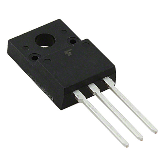
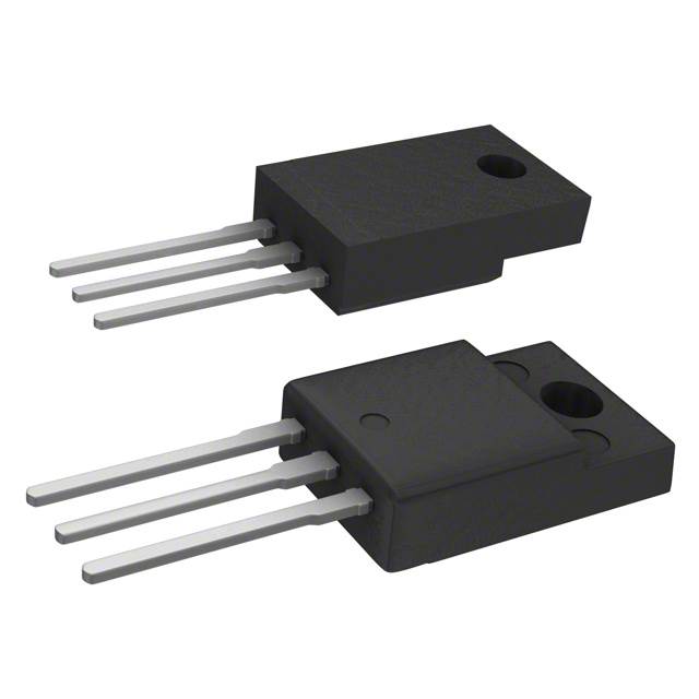
The FDPF10N50FT is an N-Channel MOSFET manufactured by onsemi, rated for 500V drain-to-source voltage and 9A continuous drain current in a Through Hole TO-220F-3 package. This device is classified as Obsolete, making identification of equivalent and substitute parts essential for ongoing production support and design continuity.
The FDPF10N50FT operates within the UniFET™ series and is RoHS3 compliant. Due to its obsolete status, substitute parts must maintain electrical and mechanical compatibility across critical parameters including voltage rating, current capacity, on-resistance characteristics, and thermal performance.
Substiute Parts
Key Parameters
| Parameter | Value | Specification Basis |
|---|---|---|
| Drain to Source Voltage (Vdss) | 500 V | Maximum voltage rating |
| Continuous Drain Current (Id) @ 25°C | 9A (Tc) | Maximum continuous current capacity |
| On-Resistance (Rds On Max) @ Id, Vgs | 850 mOhm @ 4.5A, 10V | Conduction loss characteristic |
| Gate Threshold Voltage (Vgs(th) Max) @ Id | 5V @ 250µA | Gate drive requirement |
| Gate Charge (Qg Max) @ Vgs | 24 nC @ 10V | Switching speed characteristic |
| Power Dissipation (Max) | 42W (Tc) | Thermal capability |
| Operating Temperature Range | -55°C ~ 150°C (TJ) | Junction temperature limits |
| Mounting Type | Through Hole | PCB assembly compatibility |
| Package / Case | TO-220-3 Full Pack | Physical form factor |
Substitute Part Grouping Explanation
Substitution of the FDPF10N50FT is determined by strict adherence to the following electrical and mechanical parameters:
Primary Substitution Criteria:
- Drain to Source Voltage (Vdss): Must equal or exceed 500V
- Continuous Drain Current (Id): Must equal or exceed 9A at rated conditions
- On-Resistance (Rds On): Must not exceed 850 mOhm at specified gate voltage and current
- Gate Threshold Voltage (Vgs(th)): Must be compatible with 10V drive voltage
- Power Dissipation: Must support thermal requirements of the application
- Mounting Type: Must be Through Hole
- Package: Must be TO-220-3 compatible form factor
Compliance Requirements:
- RoHS3 compliance mandatory
- REACH compliance status must be unaffected or compliant
Substitute parts are classified into two categories based on their relationship to the main part:
Direct Substitutes: Parts that meet or exceed all primary electrical parameters and maintain full functional equivalence.
Similar Substitutes: Parts that meet core voltage and current requirements but may have variations in secondary parameters such as on-resistance, gate charge, or power dissipation. These require application-level verification of thermal and switching characteristics.
Parameter Comparison
| Parameter | FDPF10N50FT (Main) | TK10A50D(STA4,Q,M) | R5009ANX | STP9NK50ZFP | TK8A50D(STA4,Q,M) | ZDX080N50 |
|---|---|---|---|---|---|---|
| Manufacturer | onsemi | Toshiba | Rohm | STMicroelectronics | Toshiba | Rohm |
| Vdss (V) | 500 | 500 | 500 | 500 | 500 | 500 |
| Id @ 25°C (A) | 9 (Tc) | 10 (Ta) | 9 (Tc) | 7.2 (Tc) | 8 (Ta) | 8 (Tc) |
| Rds On Max (mOhm) | 850 @ 4.5A, 10V | 720 @ 5A, 10V | 720 @ 4.5A, 10V | 850 @ 3.6A, 10V | 850 @ 4A, 10V | 850 @ 4A, 10V |
| Vgs(th) Max (V) @ Id | 5 @ 250µA | 4 @ 1mA | 4.5 @ 1mA | 4.5 @ 100µA | 4 @ 1mA | 4 @ 1mA |
| Qg Max (nC) @ 10V | 24 | 20 | 21 | 32 | 16 | 23 |
| Ciss Max (pF) @ 25V | 1170 | 1050 | 650 | 910 | 800 | 1120 |
| Power Dissipation Max (W) | 42 (Tc) | 45 (Tc) | 50 (Tc) | 30 (Tc) | 40 (Tc) | 40 (Tc) |
| Operating Temp Range (°C) | -55 ~ 150 | 150 (TJ) | 150 (TJ) | -55 ~ 150 | 150 (TJ) | 150 (TJ) |
| Package | TO-220F-3 | TO-220SIS | TO-220FM | TO-220FP | TO-220SIS | TO-220FM |
| Product Status | Obsolete | Active | Not For New Designs | Active | Active | Not For New Designs |
| RoHS3 Compliance | Yes | Yes | Yes | Yes | Yes | Yes |
Engineering Selection Recommendations
Direct Substitution - Recommended for New Designs:
TK10A50D(STA4,Q,M) (Toshiba Semiconductor and Storage) is the primary recommended substitute. This device exceeds the FDPF10N50FT specification with 10A continuous drain current versus 9A, improved on-resistance of 720 mOhm, and higher power dissipation capability of 45W. The part is Active status, ensuring long-term availability. RoHS3 compliance and TO-220SIS packaging provide direct mechanical compatibility. Lower gate charge (20 nC) improves switching efficiency.
Alternative Substitutes - Application-Dependent Selection:
R5009ANX (Rohm Semiconductor) matches the FDPF10N50FT electrical specification exactly with 9A continuous current and 500V rating. On-resistance is improved at 720 mOhm. Power dissipation capability is superior at 50W. However, this part carries "Not For New Designs" status, limiting its suitability for new production. Existing inventory of 9407 units supports legacy system maintenance.
TK8A50D(STA4,Q,M) (Toshiba Semiconductor and Storage) provides a lower-current alternative at 8A continuous drain current. This part is suitable only for applications where the 9A requirement can be reduced. Active product status ensures availability. On-resistance and power dissipation characteristics are comparable to the main part.
Substitutes with Reduced Current Capability:
STP9NK50ZFP (STMicroelectronics) and ZDX080N50 (Rohm Semiconductor) both operate at reduced continuous drain current (7.2A and 8A respectively) and lower power dissipation (30W and 40W). These parts are suitable only for applications where current requirements do not exceed their rated specifications. STP9NK50ZFP is Active status; ZDX080N50 is Not For New Designs.
Compliance and Availability Considerations:
All substitute parts maintain RoHS3 compliance. TK10A50D(STA4,Q,M) and STP9NK50ZFP are Active status products, ensuring long-term supply chain stability. R5009ANX and ZDX080N50 are Not For New Designs, limiting their use to legacy system support where existing inventory is available.
Frequently Asked Questions (FAQ)
Q: Can TK10A50D(STA4,Q,M) be used as a direct replacement for FDPF10N50FT in all applications?
A: Yes. TK10A50D(STA4,Q,M) meets or exceeds all electrical parameters of the FDPF10N50FT. The 10A continuous current rating exceeds the 9A requirement. On-resistance is improved, and power dissipation capability is higher. TO-220SIS packaging is mechanically compatible with TO-220-3 form factor applications. RoHS3 compliance is maintained.
Q: What is the difference between TO-220F-3, TO-220SIS, TO-220FM, and TO-220FP packages?
A: All four package variants are TO-220-3 form factors with identical pin configurations and mechanical mounting compatibility. Differences exist in internal lead frame design and thermal characteristics. TO-220SIS (Toshiba) and TO-220FM (Rohm) are standard variants. TO-220F-3 (onsemi) and TO-220FP (STMicroelectronics) are manufacturer-specific designations. All are Through Hole packages suitable for standard PCB assembly.
Q: Why does STP9NK50ZFP have lower power dissipation (30W) than the FDPF10N50FT (42W)?
A: STP9NK50ZFP is rated for 7.2A continuous current, which is lower than the FDPF10N50FT's 9A rating. Power dissipation is a function of both current capacity and thermal design. The lower current rating results in lower absolute power dissipation capability. This part is suitable only for applications where current requirements do not exceed 7.2A.
Q: Is R5009ANX suitable for new product designs?
A: No. R5009ANX carries "Not For New Designs" status, indicating that Rohm Semiconductor has designated this part for legacy support only. For new designs, TK10A50D(STA4,Q,M) or STP9NK50ZFP are recommended as both are Active status products with assured long-term availability.
Q: What does "Tc" versus "Ta" mean in the current rating specification?
A: "Tc" indicates current rating at case temperature (Tc), typically 25°C. "Ta" indicates current rating at ambient temperature (Ta). Both specifications define maximum continuous drain current under their respective thermal conditions. When comparing parts, ensure thermal conditions match the application requirements.
Q: Can TK8A50D(STA4,Q,M) replace FDPF10N50FT in a 9A application?
A: No. TK8A50D(STA4,Q,M) is rated for 8A continuous drain current, which is below the 9A requirement of the FDPF10N50FT. Using this part in a 9A application would exceed its rated current capacity and result in thermal stress and potential device failure. This part is suitable only for applications where current requirements do not exceed 8A.
Q: Are all substitute parts RoHS3 compliant?
A: Yes. All substitute parts listed in this reference maintain RoHS3 compliance, ensuring compatibility with environmental and regulatory requirements equivalent to the FDPF10N50FT.
Q: What is the significance of gate charge (Qg) differences between parts?
A: Gate charge affects switching speed and driver circuit requirements. Lower gate charge (TK8A50D at 16 nC) results in faster switching and lower driver power consumption. Higher gate charge (STP9NK50ZFP at 32 nC) requires more driver current but may provide improved noise immunity. Selection depends on the specific gate driver circuit and switching frequency requirements of the application.
Q: Can I use multiple lower-current parts in parallel to replace the FDPF10N50FT?
A: Parallel operation of MOSFETs requires careful circuit design to ensure equal current distribution and thermal management. This approach is not addressed in this substitution reference and requires detailed application-level engineering analysis beyond the scope of direct part substitution.
Alternative Parts

SJ6012L2TP
Littelfuse Inc.
6 Alternative Parts

JMK107BBJ476MA-RE
Taiyo Yuden
10 Alternative Parts

GMK107BBJ475MA-T
Taiyo Yuden
5 Alternative Parts
SJ6020N2ARP
Littelfuse Inc.
3 Alternative Parts
SJ6025R2ATP
Littelfuse Inc.
4 Alternative Parts

2474-05L
API Delevan Inc.
1 Alternative Parts

4590R-684K
API Delevan Inc.
1 Alternative Parts

CM6560R-334
API Delevan Inc.
1 Alternative Parts

CM6460-104
API Delevan Inc.
1 Alternative Parts

5526-12
API Delevan Inc.
1 Alternative Parts