


Request Quote
(Ships tomorrow)
FDP75N08A N-Channel MOSFET Equivalent & Substitute Parts
Part Overview
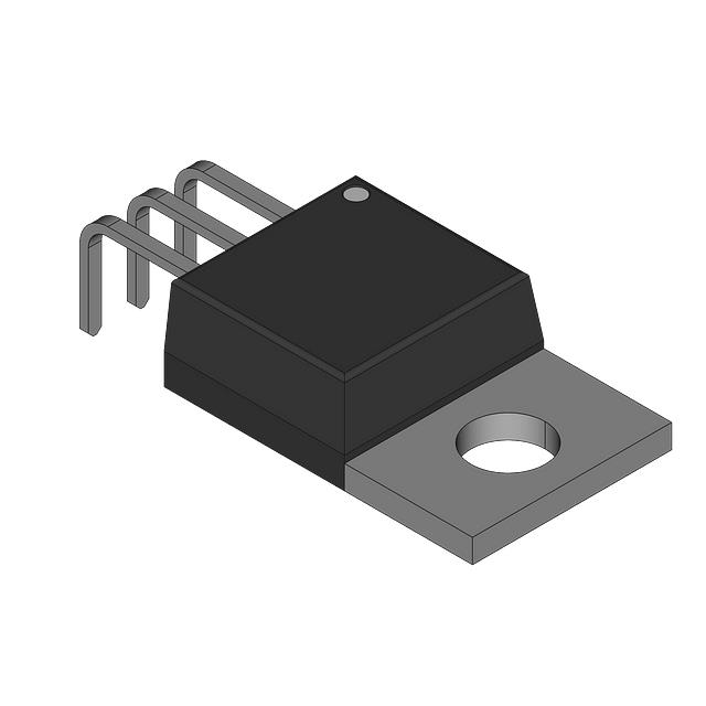
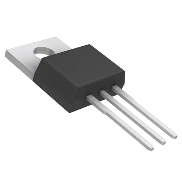
The FDP75N08A is an N-Channel MOSFET manufactured by onsemi, rated for 75V drain-to-source voltage and 75A continuous drain current in a TO-220-3 through-hole package. This device is part of the UniFET™ series and is classified as obsolete. Due to its obsolete status, equivalent and substitute parts from active product lines are necessary for new designs and ongoing production requirements. Substitute parts must maintain electrical compatibility across drain-to-source voltage, continuous drain current, on-resistance characteristics, and gate drive requirements while accommodating through-hole TO-220 package variants.
Substiute Parts
Key Parameters
| Parameter | Value | Unit |
|---|---|---|
| Drain-to-Source Voltage (Vdss) | 75 | V |
| Continuous Drain Current (Id) @ 25°C | 75 | A (Tc) |
| On-Resistance (Rds On Max) @ Id, Vgs | 11 mOhm @ 37.5A, 10V | mOhm |
| Gate Threshold Voltage (Vgs(th) Max) @ Id | 4 | V @ 250µA |
| Gate Charge (Qg Max) @ Vgs | 104 | nC @ 10V |
| Gate Voltage (Vgs Max) | ±20 | V |
| Input Capacitance (Ciss Max) @ Vds | 4468 | pF @ 25V |
| Power Dissipation (Max) | 137 | W (Tc) |
| Operating Temperature Range | -55 to 150 | °C (TJ) |
| Package Type | TO-220-3 | Through Hole |
| FET Type | N-Channel | |
| Technology | MOSFET (Metal Oxide) | |
| RoHS Status | ROHS3 Compliant |
Substitute Part Grouping Explanation
Substitute parts for the FDP75N08A are selected based on strict electrical and mechanical compatibility criteria. The primary substitution parameters are:
Critical Matching Parameters:
- Drain-to-Source Voltage (Vdss): 75V minimum
- Continuous Drain Current (Id): 75A or greater at 25°C
- On-Resistance (Rds On): Comparable performance at specified gate voltage (10V drive)
- Gate Threshold Voltage (Vgs(th)): Compatible with 4V specification
- Package Type: TO-220-3 or TO-220 through-hole variants
- FET Type: N-Channel only
- Technology: MOSFET (Metal Oxide)
Substitute parts are grouped into two categories:
Primary Substitutes (Manufacturer Recommended): Parts that directly replace the FDP75N08A with equivalent or superior electrical performance and active product status.
Similar Substitutes (Electrical Equivalents): Parts that meet the core electrical requirements but may have variations in secondary parameters such as gate charge, input capacitance, or power dissipation. These parts maintain functional compatibility within the specified operating envelope.
Parameter Comparison
| Parameter | FDP75N08A (onsemi) | IRF2807ZPBF (Infineon) | IRFB3607PBF (Infineon) | STP76NF75 (STMicroelectronics) | PHP79NQ08LT,127 (Nexperia) | PSMN012-80PS,127 (Nexperia) |
|---|---|---|---|---|---|---|
| Vdss (V) | 75 | 75 | 75 | 75 | 75 | 80 |
| Id @ 25°C (A) | 75 | 75 | 80 | 80 | 73 | 74 |
| Rds On Max (mOhm) | 11 @ 37.5A, 10V | 9.4 @ 53A, 10V | 9 @ 46A, 10V | 11 @ 40A, 10V | 16 @ 25A, 10V | 11 @ 15A, 10V |
| Vgs(th) Max (V) | 4 @ 250µA | 4 @ 250µA | 4 @ 100µA | 4 @ 250µA | 2 @ 1mA | 4 @ 1mA |
| Qg Max (nC) | 104 @ 10V | 110 @ 10V | 84 @ 10V | 160 @ 10V | 30 @ 5V | 43 @ 10V |
| Vgs Max (V) | ±20 | ±20 | ±20 | ±20 | ±15 | ±20 |
| Ciss Max (pF) | 4468 @ 25V | 3270 @ 25V | 3070 @ 50V | 3700 @ 25V | 3026 @ 25V | 2782 @ 12V |
| Power Dissipation Max (W) | 137 | 170 | 140 | 300 | 157 | 148 |
| Operating Temperature (°C) | -55 to 150 | -55 to 175 | -55 to 175 | -55 to 175 | -55 to 175 | -55 to 175 |
| Package | TO-220-3 | TO-220AB | TO-220AB | TO-220 | TO-220AB | TO-220AB |
| Product Status | Obsolete | Active | Not For New Designs | Active | Obsolete | Obsolete |
| RoHS Status | ROHS3 Compliant | ROHS3 Compliant | ROHS3 Compliant | ROHS3 Compliant | ROHS3 Compliant | ROHS3 Compliant |
Engineering Selection Recommendations
For Active Product Line Designs:
The IRF2807ZPBF (Infineon HEXFET® series) is the primary recommended substitute. This part maintains identical Vdss (75V) and Id (75A) ratings with superior on-resistance performance (9.4 mOhm vs. 11 mOhm). The IRF2807ZPBF is in active production status with extended operating temperature range (-55°C to 175°C) and ROHS3 compliance. The TO-220AB package is mechanically compatible with TO-220-3 footprints in through-hole applications.
The STP76NF75 (STMicroelectronics STripFET™ II series) provides an alternative with active product status. This part exceeds the FDP75N08A specifications with 80A continuous drain current and superior power dissipation capability (300W vs. 137W). On-resistance matches the original specification at 11 mOhm. Extended operating temperature range and ROHS3 compliance are provided.
For Existing Production Support:
The IRFB3607PBF (Infineon HEXFET® series) offers compatibility with slightly elevated current rating (80A vs. 75A) and improved on-resistance (9 mOhm). This part is classified as "Not For New Designs" but remains available for production continuity. ROHS3 compliance and extended temperature range are maintained.
For Cost-Optimized Applications:
The STP75NF75 (STMicroelectronics STripFET™ II series) provides equivalent electrical performance to STP76NF75 with active product status and extensive inventory availability (364,133 units in stock). This part is suitable for high-volume production requirements.
Package Compatibility Note:
All recommended substitutes use TO-220 or TO-220AB package variants. These packages are mechanically and electrically compatible with TO-220-3 through-hole PCB layouts. Pin configuration remains consistent across all recommended parts.
Frequently Asked Questions (FAQ)
Q: Can the IRF2807ZPBF directly replace the FDP75N08A in existing PCB designs?
A: Yes. The IRF2807ZPBF uses the TO-220AB package, which is mechanically and electrically compatible with TO-220-3 through-hole footprints. Pin assignments are identical. No PCB modifications are required.
Q: What is the primary difference between the IRF2807ZPBF and IRFB3607PBF?
A: Both parts are Infineon HEXFET® devices with 75V Vdss rating. The IRF2807ZPBF is in active production status, while the IRFB3607PBF is classified as "Not For New Designs." The IRFB3607PBF provides slightly higher current rating (80A vs. 75A) and lower on-resistance (9 mOhm vs. 9.4 mOhm). For new designs, the IRF2807ZPBF is the preferred choice.
Q: Why is the STP76NF75 rated for 300W power dissipation when the FDP75N08A is only 137W?
A: Power dissipation capability depends on thermal management design and package thermal resistance. The STP76NF75 demonstrates superior thermal performance characteristics within the TO-220 package. Both parts operate within the same voltage and current envelope. Actual power dissipation in an application is determined by on-resistance losses and circuit operating conditions, not the maximum rated value.
Q: Are all substitute parts ROHS3 compliant?
A: Yes. All recommended substitute parts listed in this document carry ROHS3 compliance certification. The FDP75N08A is also ROHS3 compliant, ensuring regulatory continuity in replacement scenarios.
Q: What is the significance of the TO-220AB package designation versus TO-220-3?
A: TO-220AB and TO-220-3 refer to the same three-pin through-hole package with identical pin spacing and mechanical dimensions. The designations reflect different manufacturer naming conventions. Both are fully compatible in PCB applications designed for TO-220 packages.
Q: Can the PHP79NQ08LT,127 be used as a substitute despite its obsolete status?
A: The PHP79NQ08LT,127 meets the electrical requirements with 75V Vdss and 73A continuous drain current. However, it is classified as obsolete. While functional compatibility exists, this part is not recommended for new designs due to supply chain risk and limited availability (6,731 units in stock). Active alternatives such as IRF2807ZPBF or STP76NF75 are preferred.
Q: What is the impact of different gate charge (Qg) values on circuit performance?
A: Gate charge affects gate drive circuit design and switching speed. The FDP75N08A specifies 104 nC at 10V. Substitute parts range from 30 nC (PHP79NQ08LT,127) to 160 nC (STP76NF75). Lower gate charge enables faster switching with reduced gate drive power requirements. Higher gate charge requires more robust gate drive circuits. Circuit compatibility depends on gate driver capability, not absolute gate charge value. Existing gate drive circuits designed for the FDP75N08A will function with substitute parts within the specified range.
Q: Is the PSMN012-80PS,127 suitable for direct replacement?
A: The PSMN012-80PS,127 meets electrical requirements with 80V Vdss (exceeds 75V requirement) and 74A continuous drain current. However, this part is classified as obsolete with limited inventory (5,878 units). The part is functionally compatible but not recommended for new designs. Active alternatives provide superior supply chain assurance.
Q: What thermal considerations apply when substituting the FDP75N08A?
A: All substitute parts are rated for extended operating temperature range (-55°C to 175°C) compared to the FDP75N08A (-55°C to 150°C). This provides additional thermal margin in applications. On-resistance values vary slightly among substitutes, affecting power dissipation. Circuit thermal design should account for the specific on-resistance of the selected substitute part. Thermal management requirements remain comparable across all recommended parts.
Alternative Parts

SJ6012L2TP
Littelfuse Inc.
6 Alternative Parts

JMK107BBJ476MA-RE
Taiyo Yuden
10 Alternative Parts

GMK107BBJ475MA-T
Taiyo Yuden
5 Alternative Parts
SJ6020N2ARP
Littelfuse Inc.
3 Alternative Parts
SJ6025R2ATP
Littelfuse Inc.
4 Alternative Parts

2474-05L
API Delevan Inc.
1 Alternative Parts

4590R-684K
API Delevan Inc.
1 Alternative Parts

CM6560R-334
API Delevan Inc.
1 Alternative Parts

CM6460-104
API Delevan Inc.
1 Alternative Parts

5526-12
API Delevan Inc.
1 Alternative Parts