


Request Quote
(Ships tomorrow)
FDN361BN N-Channel MOSFET Equivalent & Substitute Parts
Part Overview
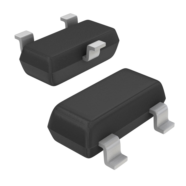
The FDN361BN is an N-Channel MOSFET manufactured by onsemi, rated for 30V drain-to-source voltage with 1.4A continuous drain current at 25°C. The device is housed in a SOT-23-3 surface mount package and features a maximum on-resistance of 110mOhm at 10V gate-source voltage. The FDN361BN is classified as obsolete, necessitating identification of functionally equivalent active alternatives for new designs and ongoing production requirements. Substitute parts must maintain compatibility across electrical ratings, thermal characteristics, and mechanical packaging while meeting current product availability and compliance standards.
Substiute Parts
Key Parameters
| Parameter | FDN361BN | Unit |
|---|---|---|
| Drain-to-Source Voltage (Vdss) | 30 | V |
| Continuous Drain Current (Id) @ 25°C | 1.4 | A |
| On-Resistance (Rds On) @ 1.4A, 10V | 110 | mOhm |
| Gate-Source Threshold Voltage (Vgs(th)) @ 250µA | 3 | V |
| Maximum Gate-Source Voltage (Vgs) | ±20 | V |
| Power Dissipation (Max) | 500 | mW |
| Operating Temperature Range | -55 to 150 | °C (TJ) |
| Package Type | SOT-23-3 | — |
| Mounting Type | Surface Mount | — |
| Product Status | Obsolete | — |
Substitute Part Grouping Explanation
Substitution eligibility for the FDN361BN is determined by the following critical parameters:
Electrical Compatibility Requirements:
- Drain-to-Source Voltage (Vdss) must equal or exceed 30V
- Continuous Drain Current (Id) must equal or exceed 1.4A at 25°C
- On-Resistance (Rds On) must not exceed 110mOhm at the specified gate-source voltage
- Gate-Source Threshold Voltage (Vgs(th)) must be compatible with 3V nominal operation
- Maximum Gate-Source Voltage (Vgs) must support ±20V operation
Mechanical and Thermal Compatibility Requirements:
- Package type must be SOT-23-3 (TO-236-3, SC-59)
- Mounting type must be Surface Mount
- Operating temperature range must span -55°C to 150°C (TJ)
- Power dissipation capability must support thermal requirements
Compliance and Availability Requirements:
- RoHS3 compliance mandatory
- Moisture Sensitivity Level (MSL) of 1 (Unlimited) required
- Active product status preferred for new designs
- Current inventory availability
The substitute parts identified below meet all electrical, mechanical, and compliance criteria established for the FDN361BN.
Parameter Comparison
| Parameter | FDN361BN | NTR4503NT1G | NVTR4503NT1G | ZXMN3A01FTA | PMV90ENER | Unit |
|---|---|---|---|---|---|---|
| Manufacturer | onsemi | onsemi | onsemi | Diodes Incorporated | Nexperia USA Inc. | — |
| Drain-to-Source Voltage (Vdss) | 30 | 30 | 30 | 30 | 30 | V |
| Continuous Drain Current (Id) @ 25°C | 1.4 | 1.5 | 1.5 | 1.8 | 3 | A |
| On-Resistance (Rds On) @ 10V | 110 @ 1.4A | 110 @ 2.5A | 110 @ 2.5A | 120 @ 2.5A | 72 @ 3A | mOhm |
| Gate-Source Threshold Voltage (Vgs(th)) @ 250µA | 3 | 3 | 3 | 1 | 2.5 | V |
| Maximum Gate-Source Voltage (Vgs) | ±20 | ±20 | ±20 | ±20 | ±20 | V |
| Power Dissipation (Max) | 500 | 420 | 420 | 625 | 460 | mW |
| Operating Temperature Range | -55 to 150 | -55 to 150 | -55 to 150 | -55 to 150 | -55 to 150 | °C (TJ) |
| Package Type | SOT-23-3 | SOT-23-3 | SOT-23-3 | SOT-23-3 | TO-236AB | — |
| Mounting Type | Surface Mount | Surface Mount | Surface Mount | Surface Mount | Surface Mount | — |
| Product Status | Obsolete | Active | Active | Active | Not For New Designs | — |
| RoHS3 Compliance | Yes | Yes | Yes | Yes | Yes | — |
| MSL Rating | 1 (Unlimited) | 1 (Unlimited) | 1 (Unlimited) | 1 (Unlimited) | 1 (Unlimited) | — |
Engineering Selection Recommendations
Primary Substitutes (Active Product Status):
The NTR4503NT1G and NVTR4503NT1G represent the most direct electrical equivalents to the FDN361BN. Both devices are manufactured by onsemi and maintain identical drain-to-source voltage (30V), gate-source threshold voltage (3V @ 250µA), and on-resistance specifications (110mOhm @ 10V). The NTR4503NT1G is available in Cut Tape and Digi-Reel packaging with 155,300 units in stock, while the NVTR4503NT1G is supplied in Tape & Reel format with automotive-grade AEC-Q101 qualification and 29,300 units in stock. Both devices are classified as Active products, making them suitable for new design implementations. The NVTR4503NT1G variant includes automotive qualification, which is beneficial for applications requiring AEC-Q101 compliance.
The ZXMN3A01FTA manufactured by Diodes Incorporated provides enhanced performance characteristics with 1.8A continuous drain current and lower on-resistance (120mOhm @ 2.5A, 10V). This device offers increased current handling capacity and improved thermal performance with 625mW power dissipation. The ZXMN3A01FTA is Active and maintains full compatibility with the FDN361BN electrical envelope. Inventory availability is 110,300 units.
Secondary Substitute (Limited New Design Use):
The PMV90ENER manufactured by Nexperia USA Inc. exceeds the FDN361BN specifications with 3A continuous drain current and superior on-resistance (72mOhm @ 3A, 10V). However, this device is classified as Not For New Designs, restricting its application to legacy system support and replacement scenarios only. The PMV90ENER is available in limited quantity (4,000 units) and should not be selected for new product development.
Compliance and Availability Summary:
All identified substitutes maintain RoHS3 compliance, MSL 1 (Unlimited) rating, and operating temperature range compatibility (-55°C to 150°C TJ). All devices are surface mount SOT-23-3 package variants suitable for direct PCB replacement. Selection between NTR4503NT1G, NVTR4503NT1G, and ZXMN3A01FTA depends on specific application requirements for current capacity, thermal performance, and automotive qualification needs.
Frequently Asked Questions (FAQ)
Q: Can the NTR4503NT1G directly replace the FDN361BN in existing designs?
A: Yes. The NTR4503NT1G maintains identical electrical specifications for drain-to-source voltage (30V), gate-source threshold voltage (3V @ 250µA), and on-resistance (110mOhm @ 10V). Both devices use SOT-23-3 surface mount packaging and support the same operating temperature range (-55°C to 150°C TJ). Pin configuration and package dimensions are compatible for direct PCB substitution.
Q: What is the difference between NTR4503NT1G and NVTR4503NT1G?
A: Both devices are electrically identical with 30V Vdss, 1.5A Id, and 110mOhm Rds On specifications. The primary difference is packaging format: NTR4503NT1G is supplied in Cut Tape and Digi-Reel format, while NVTR4503NT1G is supplied in Tape & Reel format. Additionally, NVTR4503NT1G includes automotive-grade AEC-Q101 qualification, making it suitable for automotive applications requiring this certification.
Q: Why is the ZXMN3A01FTA rated for higher current (1.8A) than the FDN361BN (1.4A)?
A: The ZXMN3A01FTA is a higher-performance variant within the same package class. The increased current rating reflects improved die design and thermal characteristics. For applications requiring only 1.4A operation, the ZXMN3A01FTA provides design margin and improved thermal performance without requiring circuit modifications.
Q: Is the PMV90ENER suitable for new product designs?
A: No. The PMV90ENER is classified as Not For New Designs by the manufacturer. This device should be used only for replacement and legacy system support. For new designs, select NTR4503NT1G, NVTR4503NT1G, or ZXMN3A01FTA.
Q: Are all substitute parts RoHS3 compliant?
A: Yes. All identified substitute parts (NTR4503NT1G, NVTR4503NT1G, ZXMN3A01FTA, and PMV90ENER) are RoHS3 compliant and carry MSL 1 (Unlimited) moisture sensitivity ratings, matching the FDN361BN compliance profile.
Q: What is the impact of different on-resistance values among substitutes?
A: On-resistance directly affects power dissipation and thermal performance. The FDN361BN and onsemi substitutes (NTR4503NT1G, NVTR4503NT1G) specify 110mOhm Rds On. The ZXMN3A01FTA specifies 120mOhm, and the PMV90ENER specifies 72mOhm. Lower on-resistance reduces power loss and heat generation. For applications operating at or near maximum current ratings, lower on-resistance provides thermal margin.
Q: Can these devices be used interchangeably in the same PCB assembly?
A: Yes, provided the application current requirements do not exceed the device rating. All substitute parts use identical SOT-23-3 package dimensions and pin configurations. PCB layout and thermal management considerations remain unchanged. Verify that the selected device's continuous drain current rating meets or exceeds the application requirement.
Q: What is the significance of gate charge (Qg) differences among substitutes?
A: Gate charge affects switching speed and gate drive circuit requirements. The FDN361BN specifies 1.8nC Qg @ 4.5V, while substitutes range from 3.9nC to 7nC. Higher gate charge requires more energy to switch the device but does not affect DC operating characteristics. For applications with fast switching requirements, lower gate charge may provide performance benefits.
Q: Are there any thermal performance differences between substitutes?
A: Yes. Power dissipation ratings differ: FDN361BN (500mW), NTR4503NT1G and NVTR4503NT1G (420mW each), ZXMN3A01FTA (625mW), and PMV90ENER (460mW). Higher power dissipation ratings indicate improved thermal performance. For applications operating at elevated ambient temperatures or with limited thermal management, devices with higher power dissipation ratings provide design margin.
Alternative Parts

SJ6012L2TP
Littelfuse Inc.
6 Alternative Parts

JMK107BBJ476MA-RE
Taiyo Yuden
10 Alternative Parts

GMK107BBJ475MA-T
Taiyo Yuden
5 Alternative Parts
SJ6020N2ARP
Littelfuse Inc.
3 Alternative Parts
SJ6025R2ATP
Littelfuse Inc.
4 Alternative Parts

2474-05L
API Delevan Inc.
1 Alternative Parts

4590R-684K
API Delevan Inc.
1 Alternative Parts

CM6560R-334
API Delevan Inc.
1 Alternative Parts

CM6460-104
API Delevan Inc.
1 Alternative Parts

5526-12
API Delevan Inc.
1 Alternative Parts