


Request Quote
(Ships tomorrow)
FDMS9410-F085 Equivalent & Substitute Parts
Part Overview
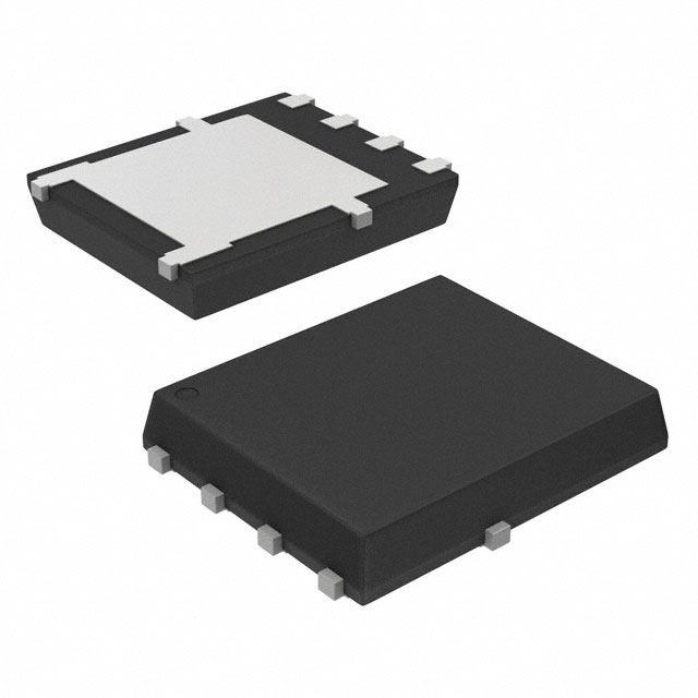
The FDMS9410-F085 is an N-Channel 40V 50A Power56 MOSFET manufactured by onsemi, designed for surface mount applications in automotive-grade power switching circuits. This device operates across a temperature range of -55°C to 175°C and delivers 75W maximum power dissipation. The part carries AEC-Q101 automotive qualification and ROHS3 compliance.
The FDMS9410-F085 is classified as obsolete. Equivalent and substitute parts are necessary to maintain design continuity, ensure supply chain availability, and support ongoing production requirements for applications utilizing this device specification.
Substiute Parts
Key Parameters
| Parameter | Value | Unit |
|---|---|---|
| FET Type | N-Channel | — |
| Drain to Source Voltage (Vdss) | 40 | V |
| Continuous Drain Current (Id) @ 25°C | 50 | A (Tc) |
| Drive Voltage (Max Rds On) | 10 | V |
| Rds On (Max) @ Id, Vgs | 4.4 | mOhm @ 50A, 10V |
| Gate Charge (Qg) (Max) @ Vgs | 36 | nC @ 10V |
| Vgs (Max) | ±20 | V |
| Power Dissipation (Max) | 75 | W (Tj) |
| Operating Temperature Range | -55 to 175 | °C (TJ) |
| Grade | Automotive | — |
| Qualification | AEC-Q101 | — |
| Mounting Type | Surface Mount | — |
| RoHS Status | ROHS3 Compliant | — |
Substitute Part Grouping Explanation
Substitution eligibility for the FDMS9410-F085 is determined by the following critical parameters:
Mandatory Matching Criteria:
- Drain to Source Voltage (Vdss): 40V
- FET Type: N-Channel
- Technology: MOSFET (Metal Oxide)
- Mounting Type: Surface Mount
- Operating Temperature Range: Minimum -55°C to 175°C
- Automotive Grade with AEC-Q101 qualification
- RoHS3 compliance
Performance Compatibility Criteria:
- Continuous Drain Current (Id) @ 25°C: Equal to or greater than 50A (Tc)
- Rds On (Max) @ 10V: Equal to or less than 4.4 mOhm
- Power Dissipation (Max): Equal to or greater than 75W (Tc)
- Gate Charge (Qg): Comparable to 36 nC @ 10V for switching performance
- Vgs (Max): ±20V or greater
The substitute parts listed below satisfy all mandatory criteria and maintain electrical performance within acceptable engineering tolerances for direct replacement in the FDMS9410-F085 application circuit.
Parameter Comparison
| Parameter | FDMS9410-F085 | IPZ40N04S55R4ATMA1 | IPC70N04S54R6ATMA1 | CSD18513Q5AT | NVMFS5C460NT1G |
|---|---|---|---|---|---|
| Manufacturer | onsemi | Infineon Technologies | Infineon Technologies | Texas Instruments | onsemi |
| FET Type | N-Channel | N-Channel | N-Channel | N-Channel | N-Channel |
| Vdss | 40V | 40V | 40V | 40V | 40V |
| Id @ 25°C (Tc) | 50A | 40A | 70A | 124A | 71A |
| Rds On (Max) @ 10V | 4.4 mOhm @ 50A | 5.4 mOhm @ 20A | 4.6 mOhm @ 35A | 5.3 mOhm @ 19A | 5.3 mOhm @ 35A |
| Gate Charge (Qg) @ 10V | 36 nC | 23 nC | 24.2 nC | 61 nC | 16 nC |
| Vgs (Max) | ±20V | ±20V | ±20V | ±20V | ±20V |
| Power Dissipation (Max) (Tc) | 75W | 48W | 50W | 96W | 50W |
| Operating Temperature Range | -55 to 175°C | -55 to 175°C | -55 to 175°C | -55 to 150°C | -55 to 175°C |
| Grade | Automotive | Automotive | Automotive | — | Automotive |
| AEC-Q101 | Yes | Yes | Yes | — | Yes |
| RoHS Status | ROHS3 Compliant | ROHS3 Compliant | ROHS3 Compliant | ROHS3 Compliant | ROHS3 Compliant |
| Mounting Type | Surface Mount | Surface Mount | Surface Mount | Surface Mount | Surface Mount |
| Product Status | Obsolete | Active | Active | Active | Active |
Engineering Selection Recommendations
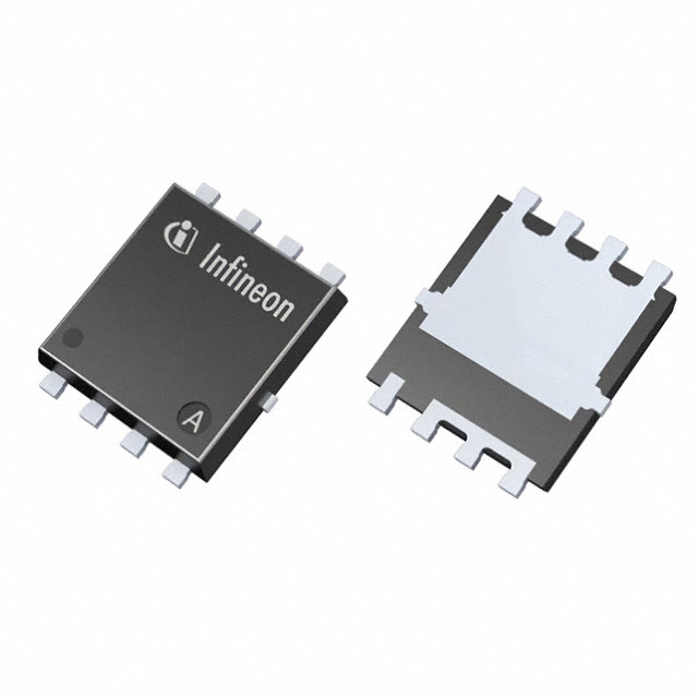
IPZ40N04S55R4ATMA1 (Infineon Technologies OptiMOS™-5)
This substitute is suitable for applications where the continuous drain current requirement is 40A or less. The device maintains full automotive qualification (AEC-Q101) and operates across the identical temperature range (-55°C to 175°C). Gate charge is lower at 23 nC, resulting in reduced switching losses. Power dissipation is rated at 48W, which is lower than the original specification. This part is active and in production, ensuring long-term availability.
IPC70N04S54R6ATMA1 (Infineon Technologies OptiMOS™)
This substitute accommodates continuous drain currents up to 70A at 25°C, exceeding the original 50A specification. Automotive qualification (AEC-Q101) and full temperature range (-55°C to 175°C) are maintained. Rds On performance is comparable at 4.6 mOhm @ 35A, 10V. Power dissipation is 50W. This part is active and in production.
CSD18513Q5AT (Texas Instruments NexFET™)
This substitute provides the highest continuous drain current rating at 124A (Tc) and maximum power dissipation at 96W, both exceeding original specifications. However, the operating temperature range is limited to -55°C to 150°C, which does not extend to the original 175°C maximum. This part does not carry explicit automotive grade or AEC-Q101 qualification in the provided data. Use is restricted to applications where the 150°C upper temperature limit is acceptable and automotive qualification is not required.
NVMFS5C460NT1G (onsemi)
This substitute is suitable for applications requiring continuous drain currents up to 71A at 25°C. Automotive qualification (AEC-Q101) and full temperature range (-55°C to 175°C) are maintained. Gate charge is the lowest among substitutes at 16 nC, minimizing switching losses. Power dissipation is 50W. This part is active and in production.
Frequently Asked Questions (FAQ)
Q: Can the IPZ40N04S55R4ATMA1 replace the FDMS9410-F085 in all applications?
A: The IPZ40N04S55R4ATMA1 is suitable for applications where the maximum continuous drain current does not exceed 40A. If your circuit requires the full 50A capability of the original part, this substitute is not appropriate. Both parts maintain identical voltage ratings, temperature ranges, and automotive qualifications.
Q: Why does the CSD18513Q5AT have a lower maximum operating temperature than the original part?
A: The CSD18513Q5AT is specified with a maximum junction temperature of 150°C, compared to 175°C for the FDMS9410-F085. Applications requiring operation at temperatures above 150°C must use alternative substitutes. Additionally, automotive qualification status is not provided for this part.
Q: What is the significance of gate charge differences among the substitute parts?
A: Gate charge (Qg) directly affects switching speed and power loss in the gate drive circuit. Lower gate charge values (such as 16 nC for NVMFS5C460NT1G and 23 nC for IPZ40N04S55R4ATMA1) result in faster switching transitions and reduced gate drive power consumption compared to the original 36 nC specification. Higher gate charge (61 nC for CSD18513Q5AT) increases switching losses.
Q: Are all substitute parts available in the same package as the FDMS9410-F085?
A: The FDMS9410-F085 uses the Power56 package (8-PowerVDFN). Substitute parts use different surface mount packages: IPZ40N04S55R4ATMA1 uses 8-PowerVDFN, IPC70N04S54R6ATMA1 uses 8-PowerTDFN (PG-TDSON-8-34), CSD18513Q5AT uses 8-PowerTDFN (8-VSONP), and NVMFS5C460NT1G uses 8-PowerTDFN (5-DFN). PCB layout modifications may be required for package changes.
Q: Which substitute part is recommended for new automotive designs?
A: For new automotive designs, select from IPC70N04S54R6ATMA1, IPZ40N04S55R4ATMA1, or NVMFS5C460NT1G. All three maintain AEC-Q101 automotive qualification and full -55°C to 175°C operating range. Selection depends on specific current requirements: IPC70N04S54R6ATMA1 for 70A capability, IPZ40N04S55R4ATMA1 for 40A capability, or NVMFS5C460NT1G for 71A capability with lowest gate charge.
Q: What is the impact of Rds On differences on circuit performance?
A: Rds On (on-resistance) directly determines conduction losses and heat generation. The FDMS9410-F085 specifies 4.4 mOhm @ 50A, 10V. Substitute parts range from 4.6 mOhm to 5.4 mOhm at comparable conditions. Higher Rds On values increase power dissipation and require thermal management verification. Lower Rds On values reduce losses and improve efficiency.
Q: Can the NVMFS5C460NT1G be used in place of the FDMS9410-F085 without circuit modifications?
A: The NVMFS5C460NT1G is electrically compatible with the FDMS9410-F085 for voltage, current, and temperature specifications. However, package differences (5-DFN versus Power56) require PCB layout changes. Gate charge is significantly lower (16 nC versus 36 nC), which may improve switching performance but requires verification that gate drive circuitry can accommodate the faster switching transitions.
Alternative Parts

SJ6012L2TP
Littelfuse Inc.
6 Alternative Parts

JMK107BBJ476MA-RE
Taiyo Yuden
10 Alternative Parts

GMK107BBJ475MA-T
Taiyo Yuden
5 Alternative Parts
SJ6020N2ARP
Littelfuse Inc.
3 Alternative Parts
SJ6025R2ATP
Littelfuse Inc.
4 Alternative Parts

2474-05L
API Delevan Inc.
1 Alternative Parts

4590R-684K
API Delevan Inc.
1 Alternative Parts

CM6560R-334
API Delevan Inc.
1 Alternative Parts

CM6460-104
API Delevan Inc.
1 Alternative Parts

5526-12
API Delevan Inc.
1 Alternative Parts