


Request Quote
(Ships tomorrow)
FDMA507PZ P-Channel MOSFET Equivalent & Substitute Parts
Part Overview
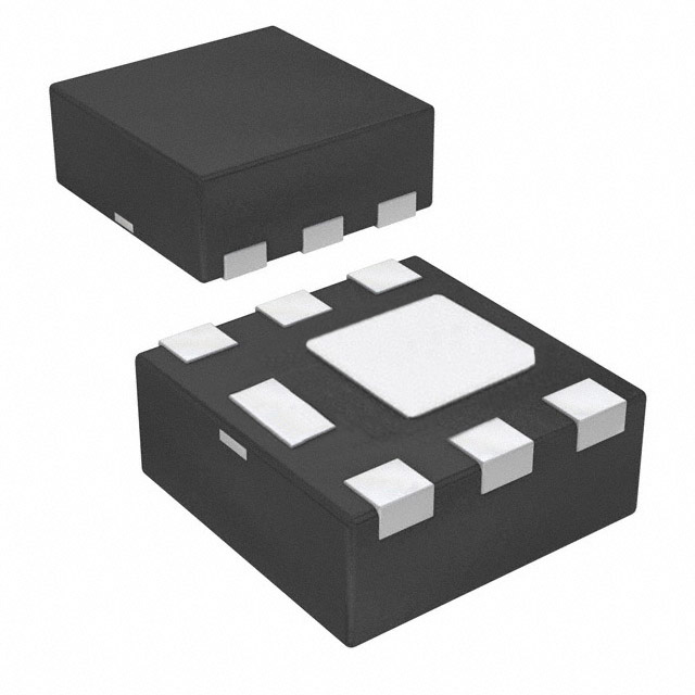
The FDMA507PZ is an active P-Channel MOSFET manufactured by onsemi, rated for 20V drain-to-source voltage with 7.8A continuous drain current at 25°C. This device is housed in a 6-MicroFET (2x2) surface mount package and is designed for applications requiring compact, high-efficiency switching in power management circuits. The part is RoHS3 compliant with unlimited moisture sensitivity level (MSL 1) and REACH unaffected status.
Substitute parts are identified when equivalent electrical performance can be maintained across critical parameters including drain-to-source voltage rating, continuous drain current capability, on-resistance characteristics, gate threshold voltage, and operating temperature range, while accommodating different package geometries and thermal specifications.
Substiute Parts
Key Parameters
| Parameter | Value | Unit |
|---|---|---|
| FET Type | P-Channel | — |
| Drain to Source Voltage (Vdss) | 20 | V |
| Current - Continuous Drain (Id) @ 25°C | 7.8 | A (Ta) |
| Rds On (Max) @ Id, Vgs | 24 | mOhm @ 7.8A, 5V |
| Vgs(th) (Max) @ Id | 1.5 | V @ 250µA |
| Operating Temperature Range | -55 to 150 | °C (TJ) |
| Mounting Type | Surface Mount | — |
| Package / Case | 6-WDFN Exposed Pad | — |
| RoHS Status | ROHS3 Compliant | — |
Substitute Part Grouping Explanation
Substitution of the FDMA507PZ is based on electrical equivalence across the following critical parameters:
Voltage Rating Equivalence: Both the main part and substitute maintain identical 20V drain-to-source voltage (Vdss) ratings, ensuring compatibility in circuits designed for this voltage class.
Current Capability: The substitute part (PMPB20XPE,115) provides 7.2A continuous drain current, which is within 92% of the main part's 7.8A rating. This current differential is acceptable for applications where the circuit design accommodates the substitute's current specification.
On-Resistance Performance: The substitute exhibits 23.5 mOhm on-resistance at 7.2A and 4.5V gate-source voltage, compared to the main part's 24 mOhm at 7.8A and 5V. Both devices deliver equivalent switching efficiency within standard design tolerances.
Gate Threshold Voltage: The substitute's 900 mV threshold voltage differs from the main part's 1.5V threshold. Both values fall within acceptable P-Channel MOSFET operating ranges and do not preclude functional substitution in standard gate drive circuits.
Temperature Range: Both devices operate across the identical -55°C to 150°C junction temperature range, ensuring thermal compatibility.
Compliance & Certifications: Both parts are RoHS3 compliant, REACH unaffected, and carry MSL 1 (unlimited) moisture sensitivity ratings.
Package Consideration: The substitute uses a 6-UDFN Exposed Pad package (DFN2020MD-6) versus the main part's 6-WDFN Exposed Pad package. Both are 6-pin surface mount packages with exposed thermal pads; physical footprint verification is required for PCB layout compatibility.
Parameter Comparison
| Parameter | FDMA507PZ (onsemi) | PMPB20XPE,115 (Nexperia USA Inc.) | Unit |
|---|---|---|---|
| FET Type | P-Channel | P-Channel | — |
| Technology | MOSFET (Metal Oxide) | MOSFET (Metal Oxide) | — |
| Drain to Source Voltage (Vdss) | 20 | 20 | V |
| Current - Continuous Drain (Id) @ 25°C | 7.8 | 7.2 | A (Ta) |
| Rds On (Max) @ Id, Vgs | 24 @ 7.8A, 5V | 23.5 @ 7.2A, 4.5V | mOhm |
| Vgs(th) (Max) @ Id | 1.5 @ 250µA | 0.9 @ 250µA | V |
| Gate Charge (Qg) (Max) @ Vgs | 42 @ 5V | 45 @ 4.5V | nC |
| Vgs (Max) | ±8 | ±12 | V |
| Input Capacitance (Ciss) (Max) @ Vds | 2015 @ 10V | 2945 @ 10V | pF |
| Power Dissipation (Max) | 2.4 (Ta) | 1.7 (Ta), 12.5 (Tc) | W |
| Operating Temperature Range | -55 to 150 | -55 to 150 | °C (TJ) |
| Mounting Type | Surface Mount | Surface Mount | — |
| Package / Case | 6-WDFN Exposed Pad | 6-UDFN Exposed Pad | — |
| RoHS Status | ROHS3 Compliant | ROHS3 Compliant | — |
| Moisture Sensitivity Level (MSL) | 1 (Unlimited) | 1 (Unlimited) | — |
| REACH Status | REACH Unaffected | REACH Unaffected | — |
Engineering Selection Recommendations
Primary Selection Criteria:
The FDMA507PZ remains the preferred choice for applications where the specified 7.8A continuous drain current and 24 mOhm on-resistance at 5V gate-source voltage are design requirements. The onsemi PowerTrench® series designation indicates optimized performance for the specified electrical characteristics.
Substitute Selection Criteria:
The PMPB20XPE,115 from Nexperia USA Inc. is electrically equivalent for applications where:
- Continuous drain current requirements do not exceed 7.2A
- Circuit design accommodates the substitute's 23.5 mOhm on-resistance specification
- Gate drive circuitry is compatible with the lower 900 mV threshold voltage
- PCB layout can accommodate the 6-UDFN package footprint (DFN2020MD-6) in place of the 6-WDFN package
Compliance Equivalence:
Both parts carry identical regulatory compliance: RoHS3 compliant, REACH unaffected, EAR99 ECCN classification, and MSL 1 moisture sensitivity. Both are active products with established supply chains.
Thermal Considerations:
The substitute part specifies higher thermal dissipation capability at case temperature (12.5W @ Tc) compared to the main part's 2.4W @ Ta rating. This difference reflects package geometry variations and does not preclude substitution; thermal design must account for the specific package thermal resistance characteristics.
Frequently Asked Questions (FAQ)
Q: Can PMPB20XPE,115 directly replace FDMA507PZ in all applications?
A: Direct replacement is possible only when the application's continuous drain current requirement does not exceed 7.2A and the circuit design accommodates the substitute's electrical characteristics. PCB layout must be verified for package compatibility, as the 6-UDFN and 6-WDFN packages have different footprints despite both being 6-pin surface mount devices with exposed thermal pads.
Q: What is the significance of the different gate threshold voltages (1.5V vs. 0.9V)?
A: The gate threshold voltage difference reflects different semiconductor process technologies between manufacturers. The substitute's lower threshold voltage (0.9V) indicates faster turn-on characteristics. Gate drive circuits must be verified to ensure proper operation across the substitute's threshold specification. Both values are within standard P-Channel MOSFET operating ranges.
Q: Are there thermal performance differences between these parts?
A: Yes. The FDMA507PZ is rated for 2.4W power dissipation at ambient temperature (Ta). The PMPB20XPE,115 is rated for 1.7W at Ta and 12.5W at case temperature (Tc). The substitute's higher Tc rating reflects its package design. Thermal design calculations must use the appropriate thermal resistance values for each package type.
Q: Do both parts meet the same regulatory requirements?
A: Yes. Both parts are RoHS3 compliant, REACH unaffected, carry MSL 1 (unlimited) moisture sensitivity ratings, and share the same EAR99 ECCN and HTSUS classifications. Both are active products with established supply availability.
Q: What package differences exist between these parts?
A: The FDMA507PZ uses a 6-WDFN Exposed Pad package (2x2 MicroFET form factor). The PMPB20XPE,115 uses a 6-UDFN Exposed Pad package (DFN2020MD-6 form factor). Both are 6-pin surface mount packages with exposed thermal pads. PCB layout and footprint libraries must be verified for compatibility before design implementation.
Q: How do the on-resistance specifications compare?
A: The FDMA507PZ specifies 24 mOhm on-resistance at 7.8A and 5V gate-source voltage. The PMPB20XPE,115 specifies 23.5 mOhm at 7.2A and 4.5V gate-source voltage. The substitute's slightly lower on-resistance at lower current and gate voltage indicates comparable switching efficiency. Circuit design must account for the substitute's current rating limit.
Q: Are the input capacitance values significantly different?
A: The FDMA507PZ specifies 2015 pF input capacitance at 10V. The PMPB20XPE,115 specifies 2945 pF at 10V. The substitute's higher input capacitance reflects its larger die area and different package geometry. Gate drive circuits must be evaluated to ensure adequate drive current capability for the substitute's capacitive load.
Alternative Parts

SJ6012L2TP
Littelfuse Inc.
6 Alternative Parts

JMK107BBJ476MA-RE
Taiyo Yuden
10 Alternative Parts

GMK107BBJ475MA-T
Taiyo Yuden
5 Alternative Parts
SJ6020N2ARP
Littelfuse Inc.
3 Alternative Parts
SJ6025R2ATP
Littelfuse Inc.
4 Alternative Parts

2474-05L
API Delevan Inc.
1 Alternative Parts

4590R-684K
API Delevan Inc.
1 Alternative Parts

CM6560R-334
API Delevan Inc.
1 Alternative Parts

CM6460-104
API Delevan Inc.
1 Alternative Parts

5526-12
API Delevan Inc.
1 Alternative Parts